Three Graphics Coordinate Systems
You may specify coordinates in data, device, or normal coordinate systems. These systems are explained in the following sections.
Almost all the graphics procedures will accept parameters in any of these coordinate systems. Most procedures use the data coordinate system by default. Routines beginning with the letters TV are notable exceptions. They use device coordinates by default. You can explicitly specify the coordinate system by including one of the keyword parameters Data, Device, or Normal in the call. For example:
PLOT, x, y, /Normal
Data Coordinate System
The data coordinate system is the system established by the most recent PLOT, CONTOUR, or SURFACE call. This system usually spans the plot window, the area bounded by the plot axes, with a range identical to the range of the plotted data. The system may have two or three dimensions, and may be linear, logarithmic, or semi-logarithmic.
Data is the default coordinate system for most graphics procedures.
Device Coordinate System
The device coordinate system is the physical coordinate system of the selected plotting device. Device coordinates are integers, ranging from (0,0) at the bottom-left corner, to (Vx – 1, Vy – 1) at the upper-right corner. Vx and Vy are the number of columns and rows addressable by the device.
Normal Coordinate System
The normalized coordinate system ranges from (0.0, 0.0) to (1.0, 1.0) over the three axes.
Coordinate System Conversion
This section describes how PV‑WAVE converts from one coordinate system to another.
The system variables !D, !P, !X, !Y, and !Z contain the information necessary to convert from one coordinate system to another. The relevant fields of these system variables are explained below, and formulas are given for conversions to and from each coordinate system. Three-dimensional coordinates are discussed in
Displaying 3D Data.
In the following discussion, D is a data coordinate, N is a normalized coordinate, and R is a raw device coordinate.
The fields !D.X_VSize and !D.Y_VSize always contain the size of the visible area of the currently selected display or drawing surface. Let Vx and Vy represent these two sizes.
The field !X.S, is a two-element array that contains the parameters of the linear equation converting data coordinates to normalized coordinates. !X.S(0) is the intercept, and !X.S(1) is the slope. !X.Type is 0 for a linear x–axis, and is 1 for a logarithmic x–axis. The y– and z–axes are handled in the same manner, using the system variables !Y and !Z.
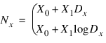
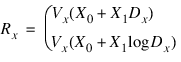
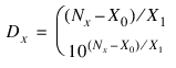
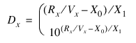
With the above variables defined, the two-dimensional coordinate conversions for the x coordinate may be written as follows:
Dx = Data coordinate
Nx = Normalized coordinate
Rx = Device coordinate
Vx = Device X size, in device coordinates
Xi = !X.S(i), scaling parameter
Data to Normal conversion:
Data to Device conversion:
Normal to Device conversion:
Rx = NxVx
Normal to Data conversion:
Device to Data conversion:
Device to Normal conversion:
Nx = Rx / Vx
The y– and z–axis coordinates are converted in exactly the same manner, with the exception that there is no z device coordinate and logarithmic z-axes are not permitted.
Version 2017.1
Copyright © 2019, Rogue Wave Software, Inc. All Rights Reserved.