Image Display Routines: TV and TVSCL
The TV and TVSCL procedures display images on the screen. They take the same arguments and keywords, and differ only in that TVSCL scales the image into the intensity range of the display device, while TV displays the image directly.
For details on the keywords for a particular routine, see the routine’s description in the PV‑WAVE Reference.
note | Because Windows reserves 20 out of the available 256 colors, you might achieve better results displaying color images with the TVSCL procedure. TVSCL automatically scales the color intensities to the full range of available colors. |
Image Orientation on the Display Screen
The coordinate system of the image display screen is oriented with the origin, (0, 0), in the lower-left corner. The upper-right-hand corner has the coordinate (Xsize – 1, Ysize – 1), where Xsize and Ysize are the dimensions of the visible area of the window or display. The descriptions of the image display routines that follow assume a window size of 512-by-512, although other sizes may be used.
!Order is a system variable that controls the order in which the image is written to the screen. Images are normally output with the first row at the bottom (i.e., in bottom to top order), unless !Order is one, in which case, images are written on the screen from top to bottom. The Order keyword can also be specified with the TV and TVSCL routines. It works in the same manner as !Order except that its effect only lasts for the duration of the single call—the default is that specified by !Order.
An image may be displayed with any of the eight possible combinations of axis reversal and transposition by combining the display procedures with the ROTATE function.
Image Position on the Display Screen
Image positions run from the left of the screen to the right and from the top of the screen to the bottom. If a position number is used instead of X and Y, the position of the image is calculated from the dimensions of the image as follows:
Xsize, Ysize = size of display or window
Xdim, Ydim = dimensions of array
Nx = Xsize / Xdim = number of images across the screen
X = XdimPositionmoduloNx = starting X value
Y = Ysize – Ydim[1 + Position / Nx ] = starting Y value
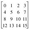
For example, when displaying 128-by-128 images on a 512-by-512 window or display, the position numbers run from 0 to 15 as follows:
Image Size
Most image devices have a fixed number of display pixels. Common sizes are 512 x 512, and 1280 x 1024. Such pixels have a fixed size which cannot be changed. For such devices, the area written on the screen is the same size as the dimensions of the image array. One-dimensional vectors are considered as row vectors. The X and Y parameters specify the coordinates of the lower-left corner of the area written on the display.
There are some devices, however, that can place an image with any number of pixels into an area of arbitrary size. PostScript devices are a notable example. These devices are said to have scalable pixels, because there is no direct connection between the number of pixels in the image and the physical space it occupies in the displayed image. When the current image device has scalable pixels, PV‑WAVE sets the first bit of !D.Flags. The following statement can be used to determine if the current device has scalable pixels:
SP = !D.Flags AND 1
SP will be nonzero if the device has scalable pixels. When displaying an image on a device with scalable pixels, the default is to use the entire display surface for the image. The XSize and YSize keywords can be used to override this default and specify the width and height that should be used.
The XSize and YSize keywords should also be used when positioning images with the position argument to TV or TVSCL. Position normally uses the size of the image in pixels to determine the placement of the image, but this is not possible for devices with scalable pixels. Instead, the default for such devices is to assume a single position that fills the entire available display surface. However, if Xsize and Ysize are specified, Position will use them to determine image placement.
Examples
; Set all display memory to 100.
TV, REPLICATE(100B, 512, 512)
; Define a 50-column by 100-row array.
ABC = BYTARR(50,100)
; Display array ABC starting at location x=300, y=400. Display
; pixels in columns 300 to 349, and rows 400 to 499 are zeroed.
TV, ABC, 300, 400
; Display image divided by 2 at position number 12.
TV, ABC/2, 12
; Output image to memory channel 2, lower-left corner at
; (256, 256).
TV, ABC, 256, 256, 2
; Assume file one contains a sequence of 64-by-64 byte arrays
AA = ASSOC(1, BYTARR(64,64))
; Display 64 images from file, from left to right and top to
; bottom, filling a 640-by-512 area.
FOR I=0, 63 DO TV, AA(I), I
Version 2017.1
Copyright © 2019, Rogue Wave Software, Inc. All Rights Reserved.