POLYWARP Procedure
Standard Library procedure that calculates the coefficients needed for a polynomial image warping transformation.
Usage
POLYWARP, xd, yd, xin, yin, deg, xm, ym
Input Parameters
xd — The vector containing the x-coordinates to be fit as a function of (xin, yin).
yd — The vector containing the y-coordinates to be fit as a function of (xin, yin).
xin — The vector containing the independent x-coordinates. Must have the same number of points as xd.
yin — The vector containing the independent y-coordinates. Must have the same number of points as yd.
deg — The degree of the polynomial to be fitted to the data. The number of coordinate pairs formed by xin and yin must be greater than or equal to (deg + 1)2.
Output Parameters
xm — A (deg + 1)-by-(deg + 1) array containing the coefficients of xd as a function of (xin, yin).
ym — A (deg + 1)-by-(deg + 1) array containing the coefficients of yd as a function of (xin, yin).
Keywords
None.
Discussion
POLYWARP calculates its transformation coefficients using the polynomial least-squares method. It returns the coefficients of the polynomial functions which best approximate the data:

The
xm polynomial array pertains to the
x direction.
The
ym polynomial array pertains to the
y direction.
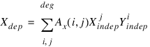
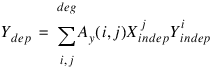
POLYWARP determines the coefficients Ax(i, j) and Ay(i, j) of these two polynomial functions:
and:
where Ax = xm and Ay = ym.
note | The xm (x-coefficients) and ym (y-coefficients) can be used as input for the POLY_2D function. POLY_2D performs the actual warping of the image, using the x and y transformation coefficients that you provide. |
Example
PRO polywarp_ex1
; Create a test image and display it.
image = BYTSCL(DIST(300))
WINDOW, XSize=300, YSize=300
TV, image
; Create arrays describing four independent control points and
; plot these on top of image. These points describe a
; square, and represent the position of points in a
; calibration image.
xin = [100, 200, 200, 100]
yin = [200, 200, 100, 100]
XYOUTS, 100, 200, '0', /Device
XYOUTS, 200, 200, '1', /Device
XYOUTS, 200, 100, '2', /Device
XYOUTS, 100, 100, '3', /Device
xd = INTARR(4)
yd = INTARR(4)
; Pick four dependent warping control points from image;
; these points represent calibration points as actually
; measured by an instrument, which, due to distortion,
; has warped them.
FOR i=0L,3 DO BEGIN
PRINT, 'Pick warped point ', i
CURSOR, xt, yt, /Device
WAIT, 0.5
xd(i) = xt
yd(i) = yt
ENDFOR
deg = 1
; Perform linear (first degree) warping. POLYWARP returns
; xm and ym, the coefficients of the polynomial functions
; which describe this warping.
POLYWARP, xd, yd, xin, yin, deg, xm, ym
; Apply the polynomial functions calculated with POLYWARP
; to the first image, using bilinear interpolation.
interp = 1
result = POLY_2D(image, xm, ym, interp)
; Display the resulting image, which represents the image
; after correcting for instrument distortion.
TVSCL, result
END
See Also
For more information on image processing, see Chapter 5, Displaying 3D Data, in the PV‑WAVE User’s Guide.
For additional information, see the section Geometric Transformations in Chapter 6 of the PV‑WAVE User’s Guide.
Version 2017.1
Copyright © 2019, Rogue Wave Software, Inc. All Rights Reserved.