TV Procedure
Displays images without scaling the intensity.
Usage
TV, image[, x, y[, channel ]]
TV, image[, position]
Input Parameters
image—A vector or two-dimensional matrix to be displayed as an image.
If image is not already of byte type, it is converted prior to use, although the conversion may distort the data contained in the image.
note | To insure data integrity, use the TVSCL procedure instead of TV. TVSCL does a byte scaling before displaying the image. |
x, y—(optional) The lower-left x- and y-coordinates of displayed image.
channel—(optional) The memory channel to be written. If not specified, it is assumed to be zero. This parameter is ignored on display systems that have only one memory channel.
position—(optional) A number specifying the position of the image. Positions run from the left of the window to the right, and from the top of the window to the bottom (see the Discussion section for details).
Keywords
Centimeters—If present, specifies that all position values (the x y parameters and the XSize and YSize keywords) are in centimeters from the origin. This is useful when dealing with devices that do not provide a direct relationship between image pixels and the size of the resulting image, such as PostScript printers.
If Centimeters is not present, position values are taken to be in device coordinates.
Channel—The memory channel to be written. This keyword is identical to the channel input parameter; only one needs to be used.
Data—If present, specifies that all position and size values are in data coordinates. This is useful when drawing an image over an existing plot, since the plot establishes the data scaling.
Device—If present, specifies that all position and size values are in device coordinates. This is the default.
Inches—If present, specifies that all position and size values are in inches from the origin. This is useful when dealing with devices that do not provide a direct relationship between image pixels and the size of the resulting image, such as PostScript printers.
Normal—If present, specifies that all position and size values are in normalized coordinates in the range 0.0 to 1.0. This is useful when you want to draw an image in a device-independent manner.
Order—If specified, overrides the current setting of the !Order system variable for the current image only. If nonzero, Order causes the image to be drawn from the top-down, instead of from the bottom-up (the default).
True—(UNIX) If present and nonzero, indicates that a true-color (24-bit) image is to be displayed and specifies the index of the dimension over which color is interleaved:

1—Displays pixel-interleaved images of dimensions (3,
m, n).
2—Displays row-interleaved images of dimensions (
m, 3,
n).
3—Displays image-interleaved images of dimensions (
m, n, 3). (Image interleaving is also known as band interleaving.)
note | To use True, the image parameter must have three dimensions, one of which is equal to 3. |
XSize—The width of the resulting image. This keyword is intended for devices with scalable pixel size (such as PostScript), and is ignored by pixel-based devices that are unable to change the size of their pixels.
YSize—The height of the resulting image, with the same limitations as XSize.
Z—The z position. The value of z is of use only if the three-dimensional transformation is in effect via the T3d keyword.
Discussion
Because Windows reserves 20 out of the available 256 colors, you might achieve better results displaying color images with the TVSCL procedure. TVSCL automatically scales the color intensities to the full range of available colors.
If position is used instead of the x and y parameters, the position of the image is calculated based on the largest grid of images of this size that will fit on the display, numbered from left to right and top to bottom. Specifically, the position is calculated as explained below.
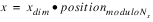
The starting x-coordinate position is defined as:
The starting y-coordinate position is defined as:
where:
YSize is the height of the display or window
xdim and
ydim are the dimensions of the array
images across the display surface are defined as:
For example, when displaying 128-by-128 images on a 512-by-512 display, the position numbers run from 0 to 15 as follows:
Example 1
; Read the image.
mandril = BYTARR(512, 512)
OPENR, unit, !Data_dir + 'mandril.img', /Get_lun
READU, unit, mandril
FREE_LUN, unit
WINDOW, XSize=512, YSize=512
; Display the image.
TV, mandril
WAIT, 1
; Display image from bottom-up instead of top-down;
; this inverts the image.
WAIT, 1
TV, mandril, /Order
WAIT, 1
; Interpolate a smaller image of size 100-by-100 pixels.
small_img = CONGRID(mandril, 100, 100)
; Create contour plot of data and overlay the image at the origin,
; specifying the image position in data coordinates.
CONTOUR, small_img
TV, small_img, 0, 0, /Data
WAIT, 1
; Tile entire window with images, using the position parameter
; rather than specifying X and Y locations.
FOR i=0L, 24 DO TV, small_img, i
Example 2
This example uses TV in conjunction with the REBIN and CONGRID procedures to enlarge small images.
; Create the data.
data = BYTSCL(DIST(60))
; Display the data.
WINDOW, Xsize=480, Ysize=480, XPos=50, YPos=50, /Free
TV, data
; Load a color table.
LOADCT, 5
; Enlarge the original data.
enlarge = REBIN(data, 480, 480)
; Display the area enlarged with REBIN.
WINDOW, Xsize=480, Ysize=480, XPos=150, YPos=150, /Free
TV, enlarge
enlarge = REBIN(data, 480, 480, /Sample)
; Redisplay area enlarged with REBIN using the nearest
; neighbor method for the sampling.
WINDOW, Xsize=480, Ysize=480, XPos=250, YPos=250, /Free
TV, enlarge
; Display the area enlarged with CONGRID.
enlarge = CONGRID(data, 480, 480)
WINDOW, Xsize=480, Ysize=480, XPos=350, YPos=350, /Free
TV, enlarge
; Redisplay the area enlarged with CONGRID using the
; bilinear interpolation method for the sampling.
enlarge = CONGRID(data, 480, 480, /Interp)
WINDOW, Xsize=480, Ysize=480, XPos=450, YPos=450, /Free
TV, enlarge
See Also
For more information, see the PV‑WAVE User’s Guide.
Version 2017.1
Copyright © 2019, Rogue Wave Software, Inc. All Rights Reserved.