Manipulating Components
Selection
By default, an Objective Views application starts in selection mode. If you are not in selection mode, you can switch to it by clicking the
Selection tool button

.
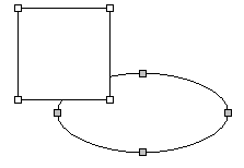
You can select a single component by clicking it while selection mode is activated. If you want to select multiple components, hold the CTRL key and then click each of the components you want to include in the selection, or click and drag on empty space to draw a selection rectangle. The last component selected for a multiple selection is distinguished from the others by its gray selection handles. The gray handles are used to indicate that it is an anchor component. Objective Views uses anchor components as a reference for alignment operations. If you want another component to serve as the anchor, hold the CTRL key and then click on another component within the selection. Objective Views transfers the gray handles from the previous component to the selected component.
To deselect a single component from a group, press the SHIFT key and click the component you want to exclude from the selection.
Movement
When the application is in selection mode, you can move selected components by clicking them and dragging the mouse. When you place the pointer over a component that you can move, the mouse pointer changes to a can move pointer. If the Snap to Grid option in the Viewport is enabled, the top left corner of the component’s bounding box aligns with the grid.
You can move the selected Components slightly using the nudge operations. These commands move the Components one unit by default and five units if you are holding the SHIFT key. These commands are as follows:
Nudge Up | |
Nudge Down | |
Nudge Left | |
Nudge Right | |
You can easily line up multiple components using the alignment operations. You can align a component by any edge or by its center. The anchor component in a multiple selection, which is distinguished by its gray selection handles, is the point of reference to which all other components in the multiple selection align. These commands are as follows:
Align Top | |
Align Middle | |
Align Bottom | |
Align Left | |
Align Center | |
Align Right | |
You can also evenly space a group of components vertically or horizontally based on the position of the upper-most and lower-most component on the canvas.
Objective Views allows you to resize the height, the width or both the height and width of a group of selected components. When you select a resize button, the selected components automatically grow or shrink to match the dimensions of the anchor component, which is the last component you selected. Gray handles distinguish this component from the rest of the selected components.
Same Width | |
Same Height | |
Same Size | |
Rotation
To rotate the selected component to any angle, click the
Rotate tool button

.
When you place the cursor over a component that you can rotate, the pointer's shape changes to reflect this. Click the component you want to rotate or one of the components in a multiple selection and then drag the mouse to rotate the component or components in place. If you hold the SHIFT key while rotating, the rotation snaps to fifteen-degree increments. The same effect occurs automatically if you select the Angle Snap option in the Viewport.
There are two predefined rotation commands that you can use to rotate components ninety degrees clockwise or counter-clockwise:
Scaling
If a component is scalable, the pointer turns into a directional arrow when you place the pointer over one of the control handles on the component. Depending on which selection handle you select, you can either scale the object horizontally, vertically, or both.
If you hold the SHIFT key while you scale an object, the horizontal and vertical scale factors are always equal. If you hold the CTRL key while you scale an object, the scaling performed is relative to the center of the component.
Objective Views also includes two operations that enable you to flip the component the opposite way either horizontally or vertically.
Flip Horizontal / Flip Vertical | |
Grouping and Ungrouping Components
You can group components together to form composites with the
Group button

.
Select the components you want to group together and then click the Group button. Grouped components act like a single graphical component. Any changes you make to a composite affects each of its components. Because a composite is also considered a component, you can create a composite that is composed of other composites.
To ungroup a composite object, select the composite you want to ungroup and then click the
Ungroup button

.
Because a symbol component is treated as a single unit, you cannot ungroup it unless you open it in Symbol Designer.
Ordering Components
The individual components in a model understand the concept of a stacking (or layer) order, also known as an Z-order. Stacking order determines where each component is drawn in the stack. In other words, the order determines which component is drawn last. The last drawn component overwrites the components already on the canvas. Z-order is determined by the order in which the components are added to the model. The last component to be added is on top.
The user can change the Z-order using a set of order commands. The Bring Forward command moves a component one place in the direction of the top of the stack. The Move Back command moves a component one place in the direction of the bottom of the stack. A component can be moved directly to either the top or bottom of the stack using the Bring to Front or Send to Back commands.
Bring Forward | |
Move Back | |
Bring to Front | |
Send to Back | |
Editing Vertices
When the user selects a primitive component such as a line or a rectangle, Objective Views places control handles on every vertex that defines its shape. You can manipulate these vertices to change the shape of a component. However, these commands do not apply to all components. For example, if you have a rectangle component or a line with only two vertices, you cannot delete its vertices.
To move a vertex, position the pointer over a control handle. The cursor changes to signal that you can move this vertex. Click the control handle and then drag it to a new position. Release the mouse button to place the vertex at its new coordinates.
To insert a vertex, move the pointer between two control points and hold down the CTRL key. The cursor changes to signal that you can insert a vertex. Click the mouse button to place the vertex on the line segment.
To remove a vertex, move the pointer over a vertex and press CTRL. The cursor changes to signal that you can delete the vertex. Click the mouse button to delete the vertex from the component.