BILINTRANS Function (PV-WAVE Extreme Advantage)
Computes the bilinear transform of an analog transfer function.
Usage
result = BILINTRANS(h [, k])
Input Parameters
h—A valid analog filter structure defined as the ratio of two polynomials in positive powers of s.
k—(optional) A multiplier constant. (Default: k = 1)
Returned Value
result—A digital filter structure containing the transfer function made of a ratio of polynomials in negative powers of z.
Keywords
Newname—A scalar string specifying a name for the new filter structure. If not used, the new filter structure has the same name as the old one.
Discussion
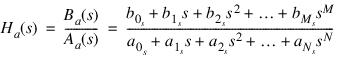
For a given analog transfer function of the form:
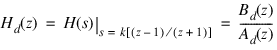
where Ba and Aa are polynomials in positive powers of s, BILINTRANS performs a bilinear transformation:
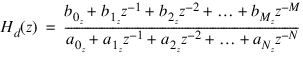
to obtain a digital rational transfer function Hd(z) in negative powers of z.
Example
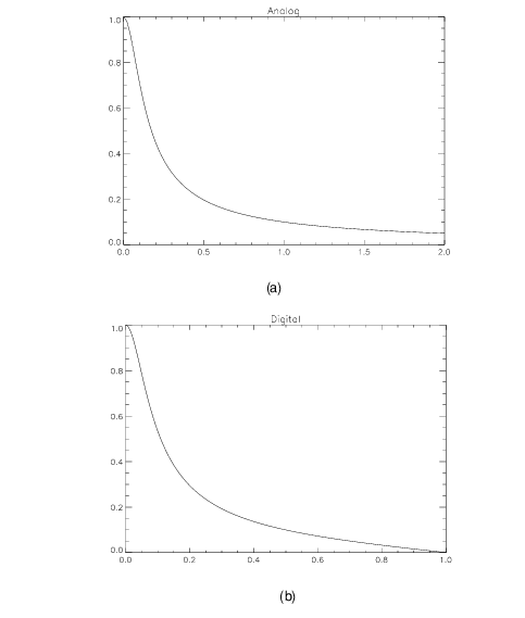
In this example we call BILINTRANS with a simple lowpass filter and plot the frequency response of both the analog and digital form of the filter.
b = [0.1]
a = [–0.1, 1.0]
; Define a simple analog lowpass filter H(s) = 0.1/(s – 0.1).
h= FILTSTR(b, a)
omega = FINDGEN(100)/50.0
; Plot the frequency response of the analog transfer function.
; See
    Frequency Response of Analog and Digital Filter (a).
PLOT, omega, ABS(FREQRESP_S(h, COMPLEX(FLTARR(100), omega))), $
Title = 'Analog'
; Transform the analog transfer function to digital.
hd = BILINTRANS(h)
hdresp = FREQRESP_Z(hd, Outfreq = f)
; Plot result.
PLOT, f, ABS(hdresp), Title = 'Digital'
; See
    Frequency Response of Analog and Digital Filter (b).
See Also
For Additional Information
Oppenheim and Schafer, 1989.
Parks and Burrus, 1987.
Proakis and Manolakis, 1988.
Roberts and Mullis, 1987.
Version 2017.0
Copyright © 2017, Rogue Wave Software, Inc. All Rights Reserved.