WAVELET Function (PV-WAVE Extreme Advantage)
Computes the wavelet transform of a data sequence using compactly supported orthonormal wavelets.
Usage
result = WAVELET(h, x, n)
result = WAVELET(h, waveletstruct, /Backwards)
Input Parameters
h—A perfect reconstruction quadrature mirror filter in a filter structure, such as may be obtained using QMFDESIGN.
Parameters specific to the forward wavelet transform (the default transform):
x—The data sequence to be transformed.
n—(scalar) The number wavelet transform levels.
Parameters specific to the backward wavelet transform (with the Backwards keyword):
waveletstruct—The output of the forward transform.
note | For the backward transform, the input parameter h must be a digital filter structure designed using QMFDESIGN. |
Returned Value
Forward wavelet transform (default):
result—A data structure containing the coefficients of the forward wavelet transform.
Backward wavelet transform (with the Backwards keyword):
result—(array) The signal reconstructed from the wavelet transform coefficients.
Keywords
Backwards—If present and nonzero, the original signal is reconstructed from the wavelet transform coefficients.
Discussion
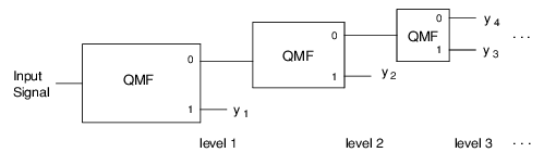
Computing the wavelet transform of a signal using a compactly supported orthornomal wavelet is equivalent to applying the quadrature mirror filter-bank structure shown in
Filter Structure for Computing Forward Wavelet Transform to the signal.
The details of how and why the structure in
Filter Structure for Computing Forward Wavelet Transform is connected to a compactly supported orthonomal wavelet are found in Akansu and Haddad, 1992; Daubechies, 1988, and 1992; Rioul and Vetterli, 1991; and Vaidyanathan, 1993.
The input and output sequences of each block in
Filter Structure for Computing Forward Wavelet Transform represents the inputs and output of the forward part of the QMF structure discussed in the procedure QMF,
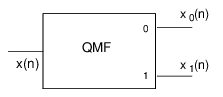
Figure 4-1: Signal Flows for Forward and Backward QMF Procedures on page 173. The specific input-output relation between each block and the filter structure shown in
Signal Flows for Forward and Backward QMF Procedures is illustrated in
Basic Computation Cell in Forward Wavelet Transform Structure.
WAVELET requires a quadrature mirror filter be supplied. Such a filter is obtained by using the QMFDESIGN function.
The output sequences x1, x2, x3, ... are the coefficients of the wavelet transform. The input parameter n specifies the number of levels of the wavelet transform structure to compute. For n levels of the wavelet transform, n + 1 output sequences are generated. WAVELET returns a PV-WAVE data structure. PARSEWAVELET provides access to the information in that data structure.
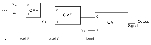
The backwards wavelet transform is computed using the filter bank structure shown in
Filter Structure for Computing Backward Wavelet Transform.
The input and output sequences of each block in
Filter Structure for Computing Backward Wavelet Transform represents the inputs and output of the backward part of the QMF structure discussed in the procedure QMF,
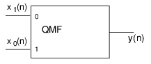
Figure 4-1: Signal Flows for Forward and Backward QMF Procedures on page 173. The specific input-output relation between each block and the filter structure in
Signal Flows for Forward and Backward QMF Procedures is illustrated in
Basic Computational Element in Backward Wavelet Transform Structure.
Example
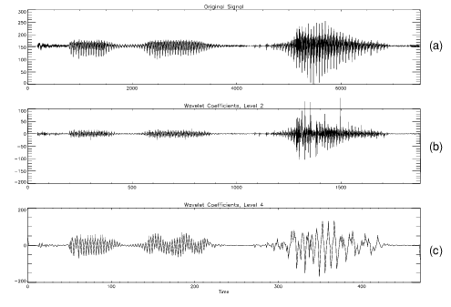
This example illustrates how to compute the wavelet transform of a speech segment. The results are shown in
Figure 4-15: WAVELET Function Example on page 220, where (a) is the plot of the original voice signal saying “PV-WAVE,” (b) is its level 2 wavelet coefficients, and (c) is its level 4 wavelet coefficients.
(UNIX) file = '$RW_DIR/sigpro-1_1/test/voice.dat'
(WIN) file = GETENV('RW_DIR')+ $
'\sigpro-1_1\test\voice.dat'
; Read in voice signal saying “PV-WAVE.”
OPENR, 1, file
x = BYTARR(7519)
READU, 1, x
CLOSE, 1
x = DOUBLE(x)
m = 5
kz = [1.d, 1.d]
; Determine coefficients of the polynomial K(z) = (1 + z–1)m to
; design Daubechies QMF that generates wavelet with m vanishing
; moments.
FOR i = 1, m-1 DO Kz = P_MULT([1.d, 1.d], kz)
; Design a QMF using the factor K(z).
h = QMFDESIGN(kz)
n = 4
; Compute a 4-level wavelet transform.
wstruct = WAVELET(h, x, n)
; Extract the different coefficient sequences from the wavelet
; data structure.
x1 = PARSEWAVELET(wstruct, 1)
x2 = PARSEWAVELET(wstruct, 2)
x3 = PARSEWAVELET(wstruct, 3)
x4 = PARSEWAVELET(wstruct, 4)
x5 = PARSEWAVELET(wstruct, 5)
!P.Multi = [0, 1, 3]
; Plot original signal and wavelet coefficients from levels 2
; and 4.
PLOT, x, XStyle = 1, Title = 'Original Signal'
PLOT, x2, XStyle = 1, Title = 'Wavelet Coefficients, Level 2'
PLOT, x4, XStyle = 1, Title = 'Wavelet Coefficients, Level 4', $
XTitle = 'Time'
; Compute the inverse wavelet transform.
y = WAVELET(h, wstruct, /Backward)
; Maximum Reconstruction Error 5.4001248e-13. Compute maximum
; error in computing forward and backward wavelet transform.
PM, MAX(ABS(x-y)), Title = 'Maximum Reconstruction Error'
See Also
For Additional Information
Akansu and Haddad, 1992. Daubechies, 1988, and 1992. Rioul and Vetterli, 1991. Vaidyanathan, 1993.
Version 2017.0
Copyright © 2017, Rogue Wave Software, Inc. All Rights Reserved.