VDA Tool Ingredients
In general, a VDA Tool is a collection of the following parts, which are managed by the VDA Tools Manager:

Unique name
Methods
Variables
Graphical elements
Attributes
User interface
PV‑WAVE underlies the VDA Tool architecture. All VDA Tool code is written in the PV‑WAVE language.
VDA Tools Require Unique Names
Once initialized with the TmInit command, the Tools Manager data structure is ready to keep track of VDA Tools. The key to this tracking system is the VDA Tool name. Each VDA Tool must be registered with the Tools Manager with a unique name. A unique name for a VDA Tool is obtained via a call to TmGetUniqueToolNames. The TmRegister function is then used to register the unique name with the Tools Manager.
Each time a VDA Tool is called, it is registered with the Tools Manager with a unique name. For example, the first instance of WzScatterPlot might be registered as WzScatterPlot_0, and the second instance might be WzScatterPlot_1.
You can always determine the names of all VDA Tool instances currently registered with the tools manager with the TmEnumerateToolNames function. The following example command shows that three separate instances of WzScatterPlot are currently registered with the Tools Manager.
PRINT, TmEnumerateToolNames()
WzScatterPlot_0, WzScatterPlot_1, WzScatterPlot_2
Methods Drive VDA Tools
A method is a procedure that is executed in response to a trigger in a VDA Tool, such as a menu or button selection or mouse click. Normally, a VDA Tool will have several methods defined for it.
When a method is executed, the Tools Manager helps direct the subsequent action. The Tools Manager keeps track of the unique instance of the VDA Tool to apply the method to, the name of the program to execute, and any data associated with that specific tool that the method procedure needs.
Register the Method
First, the method name and method procedure name must be registered with the VDA Tools Manager (see
Figure 4-5: Execution Sequence on page 145). This is usually done somewhere in the main VDA Tool procedure. The TmSetMethod function accomplishes this:
TmSetMethod, tool_name, 'TM_DISPLAY', 'WzPlotDisplay'
where tool_name is the unique name of a VDA Tool, TM_DISPLAY is the name of the method, and WzPlotDisplay is the name of the method procedure (the procedure that is executed when the method is triggered).
Execute the Method
Next, a method is executed by a TmExecuteMethod call. The VDA Tool program determines when a method is executed—this is up to the VDA Tools developer. Some predefined triggers are built into the VDA Utilities routines WoMenuBar and WoButtonBox.
TmExecuteMethod, tool_name, 'TM_DISPLAY'
Events that can trigger methods include: selecting a menu item, selecting a button from the tool bar, clicking a mouse button when the pointer is in the drawing area, exposing a window, and, potentially, many others.
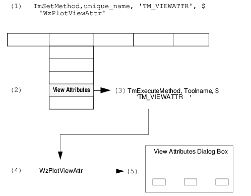
Figure 4-5: Execution Sequence on page 145 illustrates the sequence of actions that lead to the execution of a method.
Executing a method requires the following basic sequence of actions: (1) The TM_VIEWATTR method is registered with the method procedure WzPlotViewAttr in the VDA Tool source code. (2) The View Attributes menu item is selected. (3) This triggers a TmExecuteMethod command. (4) The method procedure, WzPlotViewAttr, is executed. (5) The method procedure displays the View Attributes Dialog Box.
Standard Methods
The following table lists and describes the set of “standard” VDA Tool methods. These method names are considered to be standard because they are called by default by some of the VDA Utilities (Wo) routines. Technically, you can change the names of the methods to anything you like, but you might also need to modify the callbacks for some of the VDA Utilities routines as well.
note | As a VDA Tools developer, you can create any methods you need to develop the functionality for a specific VDA Tool. For instance, if you are developing a table tool, you might not need to use the TM_DISPLAY method at all, and you would need to develop new methods designed to work with tables. |
Manipulating Variables and Other Items
Deciding which items need to be defined for a VDA Tool, along with the attributes of each item, is one of the challenges of VDA Tool development.
Items can include a wide variety of things that you want to put in a VDA Tool. Some examples of items are:
variables
help files
drawing area
file names
Each item can have characteristics, called attributes, associated with it.
Different VDA Tools might have very different sets of items, depending on the purpose of the VDA Tool. Once an item is defined and registered with the Tools Manager, the Tools Manager can always keep track of that item’s characteristics for a specific VDA Tool instance.
For example, if you are developing a surface plotting tool, you might want to provide a way for the user to change the rotation of the axes. Note that whenever the surface tool draws a surface plot, it needs to be able to extract the information from the Tools Manager that is needed to render the orientation (that is, if anything but the default rotation is to be used).
The following calls to the TmSetAttribute function assign the attributes X_ROTATION and Z_ROTATION to the global item for the tool, which is called TM. These attributes are assigned the default values of 30.
note | These calls can be placed in the main procedure of the VDA Tool to set defaults, and they can be in the procedure used to create a View Attributes dialog box. |
tmp=TmSetAttribute(tool_name, 'TM', 'X_ROTATION', 30)
tmp=TmSetAttribute(tool_name, 'TM', 'Z_ROTATION', 30)
With these orientation items registered in the Tools Manager for the item TM and unique Tool instance tool_name, the procedure associated with a method, such as the display method, can get the settings it needs to display the surface correctly. For example, the procedure called by the TM_DISPLAY method for this VDA Tool might contain the following calls:
XRot=TmGetAttribute(tool_name, 'TM', 'X_ROTATION')
ZRot=TmGetAttribute(tool_name, 'TM', 'Z_ROTATION')
Then, the returned values from these calls can be used directly in the SURFACE procedure to draw the surface:
SURFACE, var1, Ax=XRot, Az=ZRot
The following table summarizes the “standard” items and their attributes:
The important things to remember about variables, attributes, and values are:
You must register variables (or other items) and their attributes and values with the Tools Manager.
You can use Tools Manager API calls to modify or extract item attributes and values when they are needed.
You can define any items you need to provide specific functionality in a VDA Tool.
Variables and other items have attributes and values associated with them, which you also define.
Each unique VDA Tool instance has its own set of variables or other items associated with it.
Manipulating Graphical Elements
Graphical elements (also referred to as Graels) are predefined graphics routines used by VDA Tools. These routines allow you to easily add, configure, and remove graphical elements in a VDA Tool display area. The graphical elements are equivalent to items associated with specific VDA Tool instances. Graphical elements allow the VDA Tool user to draw the following graphics and text items on the fly:
Rectangle
Line
Legend
Text
Axis
Bitmap
This standard set of Graels is accessible from the standard menu bar and button bar that is provided with the VDA Utility routines WoMenuBar and WoButtonBar.
note | For the most part, VDA Tools developers do not need to be concerned with how graphical elements are created. The prewritten graphical element routines handle all aspects of drawing these graphics objects—positioning, scaling, coordinate conversion, as well as the actual drawing. Functions on the standard graphical menu and button bar have working callbacks that call the graphical element routines directly. When the user adds a graphical element to a VDA Tool plot, it is automatically registered as an item with the Tools Manager. |
To obtain the names of the graphical elements that are currently registered with a VDA Tool, use the TmEnumerateGraels function.
items = TmEnumerateGraels(tool_name)
where tool_name is the unique name of a VDA Tool instance. This function returns an array of strings containing the names of the items associated with that particular VDA Tool. Graels are returned in the following format:
graelname_num
For example, the following call shows that the VDA Tool has two variables registered with it, and several Graels: two rectangles, a line, and a legend.
PRINT, TmEnumerateGraels(tool_name)
; PV-WAVE prints the following:
; var1 var2 rectangle_0 rectangle_1 line_0 legend_0
Once you know the names of the Graels that are registered with a VDA Tool, you can use other Tools Manager routines to extract and modify their attributes and values.
For example, the following line of code obtains the names of several items, three of which are Graels: two lines and a rectangle.
PRINT, TmEnumerateGraels(tool_name)
; PV-WAVE prints: var1 var2 rectangle_0 line_0 line_2
These Graels probably have attributes, such as color, linestyle, and line thickness. You can retrieve the attributes with the TmEnumerateAttributes function. The following lines of code show that the Grael LINE_0 has three attributes associated with it: color, linestyle, and thickness.
PRINT, TmEnumerateAttributes(tool_name, 'LINE_0')
; PV-WAVE prints: COLOR LINESTYLE THICKNESS
This information can then be used to modify the Grael LINE_0. It is up to the VDA Tools developer to determine how the user can modify any item. For a Grael, you might design a View Attributes dialog box in which the user can change the characteristics of a selected Grael. The TmSetAttribute function provides the means of accomplishing this:
tmp = TmSetAttribute(tool_name, 'LINE_0', 'COLOR', value)
where value is a user-supplied value for the plot color. This value might have been obtained from a View Attributes dialog box.
Graphical Element API Routines
Functional Listing of Tools Manager Graphical Routines lists the routines used to manage graphical elements, which are primarily used to annotate plots—lines, rectangles, text, axes, and legends. They are used primarily if you want to add new graphical elements or modify existing ones, which, in general, is not necessary.
User Interface
The user interface for a VDA Tool consists of a top-level layout WAVE Widget and a collection of child widgets such as menus, buttons, drawing areas, and text areas. WAVE Widgets are described in
Using Wave Widgets.
note | The VDA Utilities are a set of convenience routines that provide high-level compound widgets for use in VDA Tools, including a menu bar, button bar, dialog boxes, and text area. These functions and their API are described in
"VDA Utilities". |
Version 2017.1
Copyright © 2019, Rogue Wave Software, Inc. All Rights Reserved.