Hardware Rendering
note | PV WAVE is now also linked to the updated Visualization Toolkit (7.1.0) and is available on Windows and Linux platforms. Use the
VTK7 OPI routines to take advantage of the improved 3D visualizations. |
note | All of the topics in this section apply to both VTK and VTK7 with the command name substitutions mentioned in section
VTK7 Visualization Toolkit OPI. |
PV‑WAVE users can create high quality, interactive graphics through the use of the PV‑WAVE link to the Visualization Toolkit (VTK). The Visualization Toolkit is an Open Source toolkit for creating both simple and complex visualizations in 3D using OpenGL, a low-level software interface to graphics hardware, for high-performance, accelerated graphics. In addition to convenience routines that have been written to access some of the more common VTK utilities, all of the functionality available in the Visualization Toolkit is available to PV‑WAVE users. The two products complement each other well. PV‑WAVE excels at data access, data manipulation, numerical algorithms, data filtering, user interface development, and many interactive 2D graphical tasks. The Visualization Toolkit is a best-of-breed tool for creating complex 3D visualizations. Together they provide a simple and quick way to build tools for Visual Data Analysis.
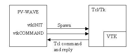
The VTK toolkit was integrated into PV‑WAVE using a Tcl shell as an intermediary. Tcl is a popular scripting language, see
www.tcl.tk for more information. The VTK toolkit already has a binding for the Tcl language. PV‑WAVE spawns a Tcl shell and communicates with it using sockets, sending VTK commands formatted for Tcl.
Creating the Tcl Shell shows how the two routines
vtkINIT and
vtkCOMMAND are used to create the Tcl shell and send commands to it, including VTK commands:
The vtkCOMMAND procedure is used in PV‑WAVE to send individual commands to the shell, and higher level wrappers have been built around this to allow many common PV‑WAVE plotting commands to be accessed in a manner similar to existing PV‑WAVE commands. Some of these commands include vtkWINDOW, vtkLIGHT, vtkPLOTS, vtkSURFACE, and vtkPOLYSHADE. The full power of the VTK visualization pipeline can still be accessed but requires specific knowledge of the VTK objects and methods.
A set of commands for packaging data into one of five supported data types in VTK is also provided, allowing data to be easily sent from PV‑WAVE to VTK.
Many procedures have a Name keyword which allows you to either choose a name for the object you are creating or return a generated one. This acts as a bridge between the high-level PV‑WAVE wrappers and low-level VTK functionality. Thus you can create a vtkSURFACE object and later use low-level VTK commands to change specific properties of this object.
Currently the VTK windows cannot be integrated into a user interface created with PV‑WAVE widgets. However, widgets can be used to size, position and annotate an object in a VTK window by passing keywords from the widget to the vtkWINDOW.
note | The PV‑WAVE link to the Visualization Toolkit is available on Windows and most UNIX platforms. |
Demonstration Programs
You can run the demonstration programs and look at the code in:
(UNIX) <RW_DIR>/vtk-3_2/demo
(WIN) <RW_DIR>\vtk-3_2\demo
Where <RW_DIR> is the main Rogue Wave directory.
These routines can be modified to work with your own data.
You can download the Visualization Toolkit and reference documentation from
public.kitware.com.
VTK7 Visualization Toolkit OPI
PV‑WAVE users can now use the improved 3D visualization capabilities and rendering engine in VTK 7.1.0 through the VTK7 OPI routines. The VTK7 toolkit is integrated into PV-WAVE using a Tcl shell as an intermediary, identical to the original VTK toolkit. The toolkit has a binding for the Tcl language and makes use of the Tcl “wrapper language” to access the VTK APIs. PV-WAVE employs a similar technique using the PV-WAVE language as the “wrapper language” for access to many common PV-WAVE commands. VTK7 can be implemented using PV-WAVE’s higher-level wrapper functions by substituting the VTK7 OPI routines for the VTK OPI routines (i.e., vtk7INIT replaces vtkINIT). This functionality is available for the following PV-WAVE procedures or functions:
vtk7INIT | vtk7WINDOW | vtk7LOOP |
vtk7COMMAND | vtk7LIGHT | vtk7BAR |
vtk7POLYSHADE | vtk7SCATTER | vtk7SURFACE |
vtk7SHOW3 | vtk7ISOSURFACE | vtk7HEDGEHOG |
vtk7STRUCTUREDPOINTS | vtk7TEXT | vtk7SLICEVOL |
vtk7CLOSE | vtk7PLOTS | vtk7GRID |
vtk7RENDERWINDOW | vtk7ADDATTRIBUTE | vtk7FORMAT |
The VTK7 OPI spawns a Tcl shell and communicates using sockets like the original VTK OPI, sending VTK commands formatted for Tcl. The two low-level routines vtk7INIT and vtk7COMMAND are used to create the Tcl shell and send commands to it, including non-PV-WAVE VTK commands. The vtk7COMMAND procedure is used in PV‑WAVE to send individual commands to the Tcl shell using the Tcl “wrapper language.”
VTK7 Backward Compatibility Issues
If you use the vtk7COMMAND to send commands to the Tcl shell, you may need to update your code for backwards-incompatible changes in the Visualization Toolkit, specifically around the pipeline objects.
Some of the more important changes are:

When establishing a pipeline connection use
SetInputConnection() instead of
SetInput().
When decoupling data objects from pipeline objects use
SetInputData() instead of
SetInput().
When getting a proxy object corresponding to the given output port use
GetOutputPort() instead of
GetOutput().
When connecting the pipeline use
SetSourceConnection() instead of
SetSource().
When directly using data objects use
SetSourceData() instead of
SetSource().
For a more complete list of the changes that may affect you, see
www.vtk.org/Wiki/VTK/VTK_6_Migration/Overview for more information regarding the VTK pipeline re-architecture.
note | The vtkXRenderWindowInteractor has changed from previous implementations on the X windows system. Linux users must manually start the interactor event loop required via vtkXRenderWindowInteractor's Initialize/Start/Enable/Disable. PV-WAVE has included the convenience routine vtk7LOOP to provide the interaction mechanism for mouse/key/time events. Please see the VTK7 OpenGL Functionality demo (wave/demo/gallery3/wd_demo39.pro) for more information. |
Initializing VTK and Managing VTK Windows
The routine vtkINIT is used to spawn a Tcl process through which VTK commands may be sent. The spawned process will continue executing until vtkCLOSE is called. Repeatedly calling vtkINIT will not cause multiple Tcl processes to be created; only one will be allowed to run at any given time for a PV‑WAVE session. You can use the /Print parameter to vtkINIT to cause debug information from the Tcl process to be logged in the PV‑WAVE console. Most VTK wrapper routines, with the exception of vtkCOMMAND and the dataset creation routines, will automatically call vtkINIT for you if you have not done so manually.
note | You must call vtkCLOSE before exiting PV‑WAVE or else an orphaned Tcl process will be left running on your machine. This process will only go away if you manually kill it or log off of your computer. |
To create a VTK window in which 3D OpenGL graphics can be rendered, use the vtkWINDOW command. It is used in a manner similar to the WINDOW command for PV‑WAVE windows. You can specify a window index to be used to refer to this window, or use /Free to allow an unused index to be chosen for you. There are two important keywords for vtkWINDOW that affect how 3D objects are displayed in it: /NoRender and /NoInteract.
Normally VTK windows operate much like PV‑WAVE windows, in that as you issue commands to add plots, annotation, axes and other objects to the window, the results are immediately rendered and displayed. For performance reasons you do not always want to do this for VTK windows, and would rather add all of the objects to be rendered before actually rendering and displaying the scene. If you specify /NoRender in a call to vtkWINDOW, then you are turning off automatic rendering until you explicitly call the vtkRENDERWINDOW routine. Use of the /NoRender routine does not affect calls to the low-level vtkCOMMAND routine.
By default VTK windows have a set of mouse interactions built into them. This allows you to rotate, zoom, and pan your view interactively. If you do not want these default interactions then specify /NoInteract with vtkWINDOW and any changes in camera view will be under programmatic control only. The default mouse interaction for VTK windows including the following features:
Keypress j / Keypress t: toggles between joystick (position sensitive) and trackball (motion sensitive) styles. In joystick style, motion occurs continuously as long as a mouse button is pressed. In trackball style, motion occurs when the mouse button is pressed and the mouse pointer moves.
Keypress c / Keypress o: toggles between camera and object (actor) modes. In camera mode, mouse events affect the camera position and focal point. In object mode, mouse events affect the actor that is under the mouse pointer.
Button 1: rotates the camera around its focal point (if camera mode) or rotate the actor around its origin (if actor mode). The rotation is in the direction defined from the center of the renderer's viewport towards the mouse position. In joystick mode, the magnitude of the rotation is determined by the distance the mouse is from the center of the render window.
Button 2: pans the camera (if camera mode) or translate the actor (if object mode). In joystick mode, the direction of pan or translation is from the center of the viewport towards the mouse position. In trackball mode, the direction of motion is the direction the mouse moves. (
Note: with 2-button mice, pan is defined as <Shift>-Button 1.)
Button 3: zooms the camera (if camera mode) or scale the actor (if object mode). Zoom in/increase scale if the mouse position is in the top half of the viewport; zoom out/decrease scale if the mouse position is in the bottom half. In joystick mode, the amount of zoom is controlled by the distance of the mouse pointer from the horizontal centerline of the window.
Keypress r: resets the camera view along the current view direction. Centers the actors and moves the camera so that all actors are visible.
Keypress s: modifies the representation of all actors so that they are surfaces.
Keypress w: modifies the representation of all actors so that they are wireframe.
The following routines operate exactly like their PV‑WAVE counterparts to manage windows:
vtkERASE—Erases the VTK window to its background color or specify a new background color.
vtkWSET—Makes a VTK window the current one to be drawn to in subsequent calls to VTK wrapper routines.
vtkWDELETE—Deletes a VTK window (but does not close the Tcl process, you still must call vtkCLOSE before exiting PV‑WAVE).
Saving the Contents of VTK Windows
In order to save the contents of VTK windows, you can use the procedure vtkPPMWRITE. This causes the current contents of the selected or current VTK window to be saved to a file in PPM (Portable PixMap) format. This is the only format supported by VTK for saving the contents of VTK windows. The corresponding function vtkPPMREAD can be used to read a PPM file and return a 24 bit image that can be displayed in PV‑WAVE. The routine vtkTVRD functions much as the PV‑WAVE TVRD routine but is a wrapper to calls to vtkPPMWRITE and vtkPPMREAD.
note | The vtkPPMWRITE procedure will save exactly what you see on your screen for a VTK window, including the contents of any windows that are partially or fully obscuring the VTK window. You must make sure the VTK window is fully visible for vtkPPMWRITE or vtkTVRD to work properly. This is a result of the underlying VTK implementation and there is not a way around this at present. |
High-level Interface Routines
The following routines are PV‑WAVE wrappers which mimic the functionality of common PV‑WAVE graphics routines. The source code for these routines are available as PV‑WAVE procedures and act as good examples of using the low-level VTK functionality.
vtkLIGHT—Adds a light source to a VTK scene
vtkCAMERA—Adds a customized camera to a VTK scene
vtkAXES—Adds a set of 3 axes to a VTK scene
vtkPLOTS—Plots 3D lines and points
vtkTEXT—Adds text annotation to a VTK scene
vtkPOLYSHADE—Displays vertex/polygon lists which describe polygonal objects
vtkSURFACE—Plots shaded and wireframe surfaces with axes
vtkSCATTER—Plots points in 3D with axes
vtkBAR—Creates a plot of 3D cylinders.
vtkCOLORBAR—Adds a color bar legend to a VTK scene using the current PV-WAVE color table.
vtkISOSURFACE—Displays the requested isosurfaces of a volume.
vtkSHOW3—Shows a 2D array three ways in a display that combines vtkSURFACE, "CONTOUR", and an image map.
vtkSLICEVOL—Creates a sliced 3D volume at specific x, y, and z locations.
vtkSURFGEN—Generates a 3D surface from sampled points assumed to lie on a surface.
Specifying Color
In the PV‑WAVE wrappers for VTK there are a number of ways to specify colors. The VTK windows always display in 24-bit color, although we can use the PV‑WAVE color table values as we will see. For parameters that expect as input a single color value, the color can be specified in any one of the following ways (in this case for the color red):
‘red’—See the file
<RW_DIR>/vtk-3_2/lib/vtkcolornames.pro for a complete list of supported color names, where
<RW_DIR> is the path to the PV‑WAVE installation.
‘FF0000’XL— Long integer hexadecimal value specifying 24-bit color.
[1.0, 0.0, 0.0]—A three element vector of normalized floating point values specifying the red, green, and blue components of the color.
[1.0, 0.0, 0.0, 1.0]—A four element vector of normalized floating point values specifying the red, green, blue, and alpha components of the color. The alpha component is the transparency where 0.0 is completely transparent and 1.0 is opaque. Transparency is not supported for all color specifications and will be ignored where not available.
2—If a short byte or short integer value is passed, the RGB color is obtained from the corresponding entry in the current PV‑WAVE color table. In this case when
TEK_COLOR has been called, color index 2 is red.
For parameters that expect as input a 1D or 2D array of color values, such as the Shades keyword for vtkSURFACE or Color keyword for vtkPOLYSHADE, the color can be specified as arrays of the above. For example for vtkSURFACE we could pass a 2D array of short integers to make use of the PV‑WAVE color table, or a (3, m, n) array of float values between 0.0 and 1.0.
Low-level Interface Routines
For many users, the above high-level VTK wrapper routines will provide sufficient functionality for creating 3D charts similar to what is already available in PV‑WAVE, but now using accelerated OpenGL graphics. Others may want to make use of the vast amount of functionality available in VTK including source code developed by other VTK users. All of this is possible using the low-level interface provided to VTK through PV‑WAVE. If you intend to use the low-level functionality available in VTK you will need to obtain documentation on VTK. See the references in
Demonstration Programs for more details.
vtkCOMMAND
Most low-level VTK functionality is accessed using vtkCOMMAND, which simply sends a text string containing any valid Tcl or VTK wrapper command to the spawned Tcl process. You can send individual commands or even invoke pre-written Tcl scripts through the “include” Tcl command.
Creation and access to VTK objects via Tcl (and thus vtkCOMMAND from PV‑WAVE) is made using this convention:
To create a VTK object in Tcl:
Vtk_class_name my_vtk_variable name
To call a method of a VTK object in Tcl:
My_vtk_variable_name method_name param_1 param_2 param_n
For example to create a VTK light source and set the color to red you could use these commands from PV‑WAVE:
vtkCOMMAND, ‘vtkLight my_light’
vtkCOMMAND, ‘my_light SetColor 1.0 0.0 0.0’
The use of the Tcl wrappers for VTK commands are documented in the references mentioned in
Demonstration Programs and in reference pages available with the VTK download. If you download the VTK distribution from
http://public.kitware.com, there are hundreds of example Tcl scripts for creating different kinds of VTK visualizations. These scripts can be used in developing PV‑WAVE wrappers to create these same visualizations from PV‑WAVE.
VTK Dataset Creation
VTK supports five basic dataset representations. These represent the different ways in which data can be organized for use in visualizations. This includes representations from simple points in 3D space, polygons, grids, and voxels (volume elements). The following PV‑WAVE wrappers offer a way to create, store, and pass these datasets to VTK:
vtkPOLYDATA
vtkRECTILINEARGRID
vtkSTRUCTUREDGRID
vtkSTRUCTUREDPOINTS
vtkUNSTRUCTUREDGRID
With all of the above dataset types, the most fundamental element is a point. In VTK there are attributes that can be associated with points and used in various ways for visualizations, such as for coloring points or drawing vectors associated with points. Creating these attributes is accomplished using the PV‑WAVE procedure vtkADDATTRIBUTE. Attributes created with this routine can be used in calls to the above five dataset creation routines. See the references in
Demonstration Programs for more details.
Simple Examples
Here are some examples of using the PV‑WAVE VTK Integration routines that show how VTK can be accessed in a manner very similar to existing PV‑WAVE graphic routines.
Example 1: Create a Surface Plot
Use the following command to create a surface plot:
vtkSURFACE, DIST(10), Shades=’slate_blue’
This one command automatically invokes vtkINIT and vtkWINDOW to open a window. Since only one color was specified (in this case using a named color), the entire surface is shaded using that color.
note | In VTK, X, Y and Z scaling are always identical, therefore you may need to scale your raw data in order to change the scaling of one direction. For example when using vtkSURFACE multiply your Z array by a scale factor so that the height of the surface is appropriate. |
Example 2: Display a Cube With a Different Color at Each Vertex
This example shows how we can use a vertex/polygon list to create a plot in much the same way as with POLYSHADE. Since the colors we specify are short integers, the colors used are from the current PV‑WAVE color table, which was loaded using TEK_COLOR in this case.
vertex_list = [[0.0, 0.0, 0.0], [1.0, 0.0, 0.0], $
[1.0, 1.0, 0.0], [0.0, 1.0, 0.0], [0.0, 0.0, 1.0], $
[1.0, 0.0, 1.0], [1.0, 1.0, 1.0], [0.0, 1.0, 1.0]]
polygon_list = [4, 0, 1, 2, 3, 4, 4, 5, 6, 7, $
4, 0, 1, 5, 4, 4, 2, 3, 7, 6, 4, 0, 4, 7, 3, 4, 1, 2, 6, 5]
TEK_COLOR
vertex_colors = [2,3,4,5,6,7,8,9]
vtkPOLYSHADE, vertex_list, polygon_list, Color=vertex_colors
Example 3: Adding an Annotation to a Scene
vtkWINDOW, /Free, Background='000077'XL, /NoRender
vtkSURFACE, HANNING(20,20)*20.0, Shades=[1.0, 0.0, 0.0, 0.5]
vtkTEXT, 'Transparent Surface', Position=[10, 10, 20], $
/Follow, Color='green'
vtkRENDERWINDOW
note | Use /NoRender to suppress rendering until everything has been added to the scene (the surface and text annotation). Also note that we specify colors in three different ways: ‘000077’XL—A long integer specifying a dark blue color [1.0, 0.0, 0.0, 0.5]—A four element array specifying the color red with a 50% transparency 'green'—A string specifying a named color, as defined in vtkcolornames.pro. |
Example 4: Debugging VTK
In this example we explicitly call vtkINIT so that we can turn on logging of all Tcl commands. We also manage the window creation and deletion and rendering ourselves.
vtkINIT, /Print
vtkWINDOW, /NoRender
vtkSCATTER, RANDOMN(seed, 3, 100), Color='blue'
vtkRENDERWINDOW
HAK, /Mesg
vtkWDELETE
vtkCLOSE
More examples are provided with the PV‑WAVE distribution.
For additional examples see the procedures in the directory <RW_DIR>/vtk-3_2/demo or <RW_DIR>/vtk7-1_0/demo (where <RW_DIR> is the path to the PV-WAVE installation).
Version 2017.1
Copyright © 2019, Rogue Wave Software, Inc. All Rights Reserved.