ERODE Function
Implements the morphologic erosion operator for shape processing.
Usage
result = ERODE(image, structure[, x0, y0])
Input Parameters
image—The array to be eroded.
structure—The structuring element. May be a one- or two-dimensional array. Elements are interpreted as binary (values are either zero or nonzero), unless the Gray keyword is used.
x0—(optional) The x-coordinates of structure’s origin.
y0—(optional) The y-coordinates of structure’s origin.
Returned Value
result—The eroded image.
Keywords
Gray—A flag which, if present, indicates that gray scale, rather than binary erosion, is to be used.
Values—An array providing the values of the structuring element. Must have the same dimensions and number of elements as structure.
Discussion
If image is not of the byte type, PV-WAVE makes a temporary byte copy of image before using it for the processing.
The optional parameters
x0 and
y0 specify the row and column coordinates of the structuring element’s origin. If omitted, the origin is set to the center,
, where
Nx and
Ny are the dimensions of the structuring element array. However, the origin need not be within the structuring element.
Nonzero elements of the structure parameter determine the shape of the structuring element (neighborhood).
If the Values keyword is not used, all elements of the structuring element are 0, yielding the neighborhood minimum operator.
You can choose whether you want to use gray scale or binary erosion:

If you select binary erosion type, the image is considered to be a binary image with all nonzero pixels considered as 1. (You will automatically select binary erosion if you don’t use either the
Gray or
Values keyword.)
If you select gray scale erosion type, each pixel of the result is the minimum of the difference of the corresponding elements of
Values overlaid with
image. (You will automatically select gray scale erosion if you use either the
Gray or
Values keyword.)
Background Information
The ERODE function implements the morphologic erosion operator on binary and gray scale images and vectors. Mathematical morphology provides an approach to the processing of digital images on the basis of shape. This approach is summarized in the description of the DILATE function. Erosion is the complement (dual) of dilation; it does to the background what dilation does to the foreground.
Briefly, ERODE returns the erosion of image by the structuring element, structure. This operation is also commonly known as contracting or reducing. It can be used to remove islands smaller than the structuring element.
The result is an image that contains items that now contract away from each other. Features that either slightly touch or are connected by narrow areas may disconnect, becoming separate, smaller objects. Any holes or gaps in or between features become larger as the features in the image shrink away from each other. Sharp-edged items and harsh angles typically become dull as they are worn away; however, in some cases areas that were dull may become somewhat sharper as a feature erodes away.
note | Erosion can be used to change the morphological structure of objects or features in an image to see what would happen if they were to actually shrink over time. |
Used with gray scale images, which are always converted to a byte type, the ERODE function is accomplished by taking the minimum of a set of differences. It may be conveniently used to implement the neighborhood minimum operator, with the shape of the neighborhood given by the structuring element.
Used with binary images, the origin of the structuring element is moved to each pixel of the image. If each nonzero element of the structuring element is contained in the image, the output pixel is set to one.
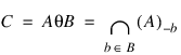
Letting A θ B represent the erosion of an image A by structuring element B, erosion may be defined as:
where (A)–b represents the translation of A by b. The structuring element B may be visualized as a probe which slides across the image A, testing the spatial nature of A at each point. Where B translated by i, j can be contained in A (by placing the origin of B at i, j), then Ai, j belongs to the erosion of A by B.
For example, when the origin of the structuring element is at (0, 0) it would look like:
0100 0000
0100 0000
1110 θ 11 = 1100
1000 0000
0000 0000
Example 1
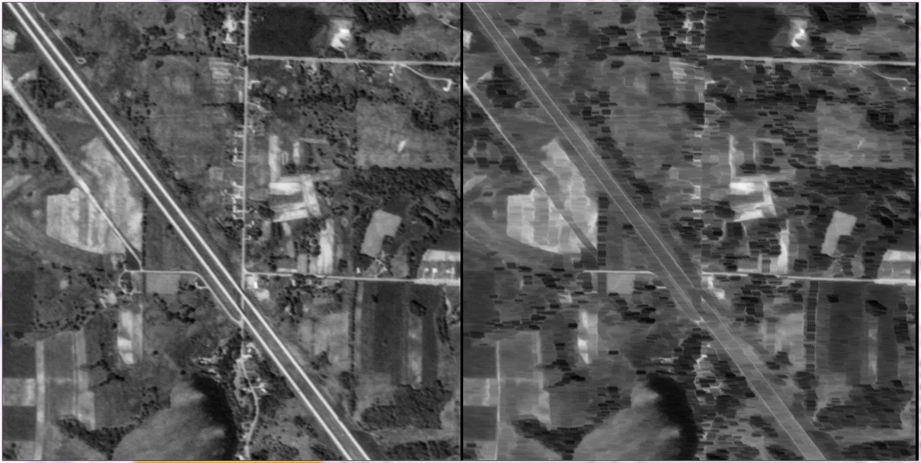
This example demonstrates what an aerial image looks like before and after applying the ERODE function three different times.
Using the ERODE Function shows the results. The image on the left is the “before” image and the image on the right is the “after” picture. For this example, the following parameters were used each time:
LOADCT, 0
OPENR, lun, !Dir + '/demo/gallery3/data/aerial_demo.img', /Get_lun
aerial_img = BYTARR(512,512)
READU, lun, aerial_img
FREE_LUN, lun
struct = [1, 0, 1]
eroded_img = ERODE(aerial_img, struct, /Gray)
eroded_img = ERODE(eroded_img, struct, /Gray)
eroded_img = ERODE(eroded_img, struct, /Gray)
eroded_img = BYTSCL(eroded_img, Min=104)
WINDOW, Xsize=1024, /Free
TVSCL, aerial_img, 2
TVSCL, eroded_img, 1
where struct has a value of [1 0 1].
See Also
Version 2017.1
Copyright © 2019, Rogue Wave Software, Inc. All Rights Reserved.