X Window System
PV‑WAVE uses the X Window System to provide an environment in which you can create one or more independent windows, each of which can be used for the display of graphics and/or images.
The X Window System is the default windowing system for UNIX PV‑WAVE platforms.
In X there are two basic cooperating processes, clients and servers. A server usually consists of a display, keyboard, and pointer (such as a mouse) as well as the software that controls them. Client processes (such as PV‑WAVE) display graphics and text on the screen of a server by sending X protocol requests across the network to the server. Although in the simplest case, the server and client reside on the same machine, this network-based design allows more elaborate configurations.
note | If you are running an X11R6 system, X Windows fonts can be rotated and transformed by general 3D transforms in PV‑WAVE. |
Controlling Where Graphics are Displayed
When you use X, the environment variable $DISPLAY (UNIX) must be set properly. Otherwise, PV‑WAVE may appear to “hang”. The following command allows PV‑WAVE windows to appear on the local display (the current workstation). Enter one of these commands at the prompt of the current workstation before you start PV‑WAVE, depending on whether you are using UNIX:
(UNIX) setenv DISPLAY nodename:0.0
You must also be sure that an X server is running on the host machine specified with the $DISPLAY environment variable, and that the machine PV‑WAVE is running on has permission to communicate with that X server. Refer to the documentation for your X-compatible window manager to learn how to modify your X server’s permissions list.
Selecting the X Driver
To use X as the current graphics device, enter the following command:
SET_PLOT, 'X'
This causes PV‑WAVE to use X for producing subsequent graphical output. Once the X driver is enabled via SET_PLOT, the DEVICE procedure is used to control its actions, as described in
"Controlling X Driver with DEVICE Keywords".
Listing the Current Settings for the X Driver
Use the command:
INFO, /Device
to view the current X driver settings.
Graphical User Interfaces (GUIs) for PV-WAVE Applications Running Under X
If you wish to include a graphical user interface (GUI) with a PV‑WAVE application that you are writing for use with the X Window System, you have several choices:
 WAVE Widgets
—A versatile, easy-to-use set of functions for creating Motif GUIs for PV‑WAVE applications. WAVE Widgets are designed for PV‑WAVE developers with little or no experience using the Motif GUI toolkits. See the PV‑WAVE
Application Developer’s Guide for detailed information on the Widget Toolbox functions.
Widget Toolbox—A set of highly flexible PV‑WAVE functions used to create Motif Graphical User Interfaces (GUIs) for PV‑WAVE applications. The Widget Toolbox functions call Motif routines directly, and are designed primarily for developers who are already experienced using either Motif. See the PV‑WAVE
Application Developer’s Guide for detailed information on the Widget Toolbox functions.
C-based Applications—PV‑WAVE can be used to add visual data analysis capability to an existing C application. The application interface can be developed in C, and, via interapplication communication functions, the C application can call PV‑WAVE to perform data processing and display functions.
note | UNIX users, for more details on interapplication communication, refer to the PV‑WAVE Application Developer’s Guide. |
note | All the options listed above are fully compatible with the X Window System and can be used to facilitate access to your application. However, you are not required to use any of them—your application can still run under X, even though it does not have a Motif GUI. |
Additional Text Formatting Commands
The following text formatting commands are new and can be used with the PostScript, WIN32, WMF, and X drivers. These commands can only be used when hardware fonts are enabled (!P.Font=0).
!FB—Switch to the bold face of the current font.
!FI—Switch to the italic face of the current font.
!FU—Underline the current font.
!FN—Switch to the normal form of the current font.
!Pxx—Switch to point size
xx of the current font, where
xx is a two digit integer (01–99).
Refer to the PV‑WAVE User’s Guide for a comprehensive list of text formatting commands.
Controlling X Driver with DEVICE Keywords
The following keywords to the DEVICE procedure provide control over the X driver:
Bypass_Translation—When this keyword is set, the translation table is bypassed and color indices can be directly specified. Pixel values read via the TVRD function are not translated if this keyword is set, and thus the result contains the actual (hardware) pixel values present in the display. By default, the translation table is used with shared color tables. When displays with static (read-only) visual classes and with private color tables are used, the translation table is
always bypassed. For more information about the translation table, refer to
"Color Translation Table".
Close_Display—Causes PV‑WAVE to sever the connection with the X server. This has the effect of deleting all generated windows from the server screen, and returns PV‑WAVE to the initial graphics state. One use for this option is to change the number of colors used. See the section,
"When Color Characteristics are Determined", for details.
Copy—Copies a rectangular area of pixels from one region of a window to another. The argument of
Copy is a six- or seven-element array: [X
s, Y
s, N
x, N
y, X
d, Y
d, W], where: (X
s, Y
s) is the lower-left corner of the source rectangle, (N
x, N
y) are the number of columns and rows in the rectangle, and (X
d, Y
d) is the coordinate of the destination rectangle. Optionally, W is the index of the window from which the pixels should be copied to the current window. If it is not supplied, the current window is used for both source and destination.
Copy can be used to increase the pace of animation. This is described in
"Using Pixmaps to Improve Application Performance".
Cursor_Crosshair—Selects the crosshair cursor type. The crosshair cursor style is the default.
Cursor_Image—Specifies the cursor pattern. The value of this keyword must be a 16-line by 16-column bitmap, contained in a 16-element short integer vector. Each line of the bitmap must be a 16-bit pattern of ones and zeros, where one (1) is white and zero (0) is black. The offset from the upper-left pixel to the point that is considered the “hot spot” can be provided via the Cursor_XY keyword.
Cursor_Original—Selects the default cursor for the window system. Under X, it is the cursor in use by the window manager when PV‑WAVE starts.
Cursor_Standard—Selects one of the predefined cursors provided by X. The available cursor shapes are defined in the file:
(UNIX) /usr/include/X11/cursorfont.h
In order to use one of these cursors, select the number of the font and provide it as the value of the Cursor_Standard keyword. For example, the cursorfont.h file gives the value of Xc_Cross as being 30. In order to make that the current cursor, use the statement:
DEVICE, Cursor_Standard=30
Cursor_XY—A two-element integer vector giving the x, y pixel offset of the cursor “hot spot”, the point which is considered to be the mouse position, from the upper-left corner of the cursor image. This parameter is only applicable if Cursor_Image is provided. The cursor image is displayed top-down—in other words, the first row is displayed at the top.
Direct_Color—When specified with a Depth value, selects the DirectColor visual with Depth bits per pixel. For example:
Direct_Color=12
The Direct_Color keyword has effect only if no windows have been created.
Floyd—If present and nonzero, selects the Floyd-Steinberg dithering method. For more information on this dithering method, the PV‑WAVE User’s Guide.
Font—Specifies the name of the font used when the hardware font is selected. For example, to select the font 8X13:
DEVICE, Font='8X13'
Usually, the window system provides a directory of font files that can be used by all applications. List the contents of that directory to find the fonts available on your system. The size of the font selected also affects the size of software-drawn text (e.g., the Hershey fonts). On some machines, fonts are kept in subdirectories of:
(UNIX) /usr/lib/X11/fonts
Get_Class—The display device's color class will be returned as a LONG number whose possible values are 2 through 5.
DEVICE, True_Color=24
DEVICE, Get_Class=class
Table B-8: Get_Class Return Values on page 2167 shows the different combinations of color class settings and the return value of
Get_Class. For example, if you set
DEVICE, Static_Gray=8,
Get_Class returns 3; if you set
DEVICE, Static_Gray=24,
Get_Class returns 4.
Get_Fontmap—Returns list of current font map settings. If /Get_Fontmap is specified, the information is printed to the screen. If a variable name is specified (e.g., Get_Fontmap=varname), a string array is returned.
The information returned by Get_Fontmap is in the same form as the strings specified with Set_Fontmap. The only exception to this pattern is that the first string returned in a string array is labeled as font 0 and is the current default font.
Get_Graphics_Function—Returns the value of the current graphics function (set with the
Set_Graphics_Function keyword). This can be used to remember the current graphics function, change it temporarily, and then restore it. For an example, see the example in the section
"Using Graphics Functions to Manipulate Color".
Get_Visuals—Displays the list of currently available visual classes. If a named variable is specified with this keyword, the information is stored in a 2D array of long values. The size of first dimension is 8, and the index is defined in the following list:
0—Visual ID
1—Visual class
2—Depth
3—Size of colormap
4—Red mask
5—Green mask
6—Blue mask
7—Significant bits in the specification
The value of visual class item is shown in the following list:
StaticGray = 0
GrayScale = 1
StaticColor = 2
PseudoColor = 3
TrueColor = 4
DirectColor = 5
The second dimension of the 2D array represents the number of available visual classes.
Get_Window_Position—Places the x and y device coordinates of the window’s lower-left corner into a named variable.
Get_Write_Mask—Specifies the name of a variable to receive the current value of the write mask. For example:
Get_Write_Mask=mask
List_Fonts—Returns a list of the available X fonts. If /List_Fonts is specified, the information is printed to the screen. If a variable name is specified (e.g., List_Fonts=varname), a string array is returned. This keyword works like the UNIX command xlsfonts. If the Pattern_Font keyword is used to specify a pattern, that pattern is used to filter the list of fonts returned by List_Fonts; otherwise, List_Fonts returns all available fonts.
Ordered—If present and nonzero, selects the Ordered method of dithering. For more information on dithering, see the PV‑WAVE User’s Guide.
Pattern_Font—Specifies a pattern that is used to filter the fonts that are returned by the List_Font keyword. For example, to list all the fonts in the adobe foundry, enter this command:
DEVICE, /List_Fonts, Pattern='-adobe-*'
DEVICE, /List_Fonts, $
Pattern_Font='-*-*-*-*-*-*-0-0-*-*-*-0-*- *'
DEVICE, /List_Fonts, $
Pattern_Font='-*-*-*-*-*-*-[1 0 0 1]-*-*-*-*-*-*-*'
In this case, the matrix is specified in the 7th field. All other fields contain the wildcard symbol (*).
note | X11R5 systems support scalable fonts. You can return the names of all scalable fonts by specifying a complete font name (one with all 14 fields separated by dashes) with a zero (0) in fields 7, 8, and 12 (the fields for pixel size, point size, and average width). To list all scalable fonts, enter the command: |
note | X11R6 systems allow fonts to be rotated and transformed by a general 3D transform. (This is accomplished using the X Logical Font Description (XLFD) extensions and does not include perspective.) You can return the names of all fonts that support 3D transformation by specifying a matrix in either the pixel size or point size fields (fields 7 or 8). To list all fonts capable of 3D transformation, enter the command: |
Pseudo_Color—When specified with a Depth value, selects the PseudoColor visual with Depth bits per pixel. For example:
Pseudo_Color=8
The Pseudo_Color keyword has effect only if no windows have been created.
Retain—Specifies the default method used for backing store when creating new windows. This is the method used when the
Retain keyword is not specified with the WINDOW procedure. Backing store and the possible values for this keyword are discussed in more detail in the subsection,
"How Is Backing Store Handled?". If
Retain is not used to specify the default method, method 1 (server-supplied backing store) is used.
Set_Character_Size—A two-element vector that changes the standard width of the vector-drawn fonts and the space allocated above the line of text. The first element in the vector contains the new character width, and the second element contains the number of pixels above the line of text. By default, characters are approximately 8-pixels wide, with 12 pixels between lines.
Set_Fontmap—Associates specific font characteristics with a particular hardware font command. This keyword can be used to specify a single string containing the information for one font, or an array of strings containing the information for multiple fonts.
For example, to associate 14 point Times bold with font command !5, use the following DEVICE call and the complete X driver font name:
Set_Fontmap='5 -adobe-times-bold-r-normal-*-14-*-*-*-*-*-*-*'
Now, whenever the !5 font command appears in a text string, the text output appears in 14 point Times bold. This keyword only affects hardware fonts (that is, when !P.Font=0).
note | A default font mapping is defined in a configuration file that is read when the X driver is initialized. For information on this configuration file, see the Fonts chapter in the PV‑WAVE User’s Guide. |
Set_Graphics_Function—X allows applications to specify the
Graphics Function. This is a logical function which specifies how the source pixel values generated by a graphics operation are combined with the pixel values already present on the screen. The complete list of possible values is given in
Table B-9: Graphics Function Values on page 2169. The default graphics function is
GXcopy, which causes new pixels to completely overwrite any previous pixels.
note | Windows hardware fonts are not affected by the current graphics function. This means that you cannot erase drawn text with an XOR operation if hardware fonts are used. This is a limitation of Windows. The only exception is the graphics function GXnoop, which works correctly. |
Set_Write_Mask—Sets the write mask to the specified value. For an
n-bit system, the write mask can range from 0 to 2
n – 1. For more information on the write mask, refer to
"Write Mask and Graphics Functions to Manipulate Color".
Static_Color—When specified with a Depth value, selects the StaticColor visual with Depth bits per pixel. This keyword has effect only if no windows have been created.
Static_Gray—When specified with a Depth value, selects the StaticGray visual with Depth bits per pixel. This keyword has effect only if no windows have been created.
Threshold—Specifies use of the threshold dithering algorithm—the simplest dithering method. For more information on this dithering method, see PV‑WAVE User’s Guide.
Translation—Using the shared colormap (which is normally recommended) causes PV‑WAVE to translate between color indices (which always start with zero and are contiguous) and the pixel values actually present in the display. The Translation keyword specifies the name of a variable to receive the translation vector. To read the translation table:
DEVICE, Translation=Transarr
The result is a 256-element byte vector,
Transarr. Element zero of
Transarr contains the pixel value allocated for the first color in the colormap, and so forth. For more information on the translation table, refer to
"Color Translation Table".
True_Color—When specified with a Depth value, selects the TrueColor visual with Depth bits per pixel. For example:
True_Color=12
The True_Color keyword has effect only if no windows have been created.
VisualID—If specified with the visual class ID number, selects the visual class with visual class with given ID number.
note | To acquire visual class ID numbers use the X library client program xdpyinfo, or use the command: DEVICE, /Get_Visuals |
Window_State—Returns an array containing values indicating the status
(open = 1, closed = 0) for all available PV‑WAVE windows. For example:
; Open window 3.
WINDOW, 3
DEVICE, Window_State=winarray
PRINT, winarray
X Window Visuals
Visuals specify how hardware deals with color. The X server of your display may provide colors or only gray scale (black and white), or both. The color tables may be changeable from within PV‑WAVE (read-write), or they may be static (read-only). The value of each pixel may be mapped to any color (Undecomposed Colormap), or certain bits of each pixel are dedicated to the red, green, and blue primary colors (Decomposed Colormap).
The X server provides six visual classes—read-write and read-only visuals for three types of displays: Gray Scale, Undecomposed Color, and Decomposed Color.
Visual Class Names lists the visual class names.
PV‑WAVE supports all six types of visual classes, although not at all possible depths (e.g., 4-bit, 8-bit, 24-bit).
note | For more information on the differences between pseudo color and 24-bit (“true” or “direct”) color, see PV‑WAVE User’s Guide. |
X servers from different manufacturers will each have a default visual class. Many servers may provide multiple visual classes. For example, a server with display hardware that supports an 8-bit deep, undecomposed, writable color map (PseudoColor), may also easily support StaticColor, StaticGray, and GrayScale visual classes.
note | For more detailed information about X visual classes, refer to Volume 1 of the Xlib Programming Manual, Second Edition, O’Reilly & Associates, Inc., Sebastopol, CA, 1990. |
Selecting a Visual Class
When opening the display, PV-WAVE asks the display for the following visual classes, in order, until a supported visual class is found:
1. DirectColor, 24-bit
2. TrueColor, 24-bit
3. PseudoColor, 8-bit, then 4-bit
4. StaticColor, 8-bit, then 4-bit
5. GrayScale, any depth
6. StaticGray, any depth
You can override this default choice by using the DEVICE procedure to specify the desired visual class and depth before you create a window.
For example, if you are using a display that supports both the 24-bit deep DirectColor visual class, and an 8-bit deep PseudoColor visual class, PV‑WAVE will select the 24-bit deep DirectColor visual class. To use PseudoColor, enter the following command before creating a window:
DEVICE, Pseudo_Color=8
note | If a visual type and depth is specified, using the DEVICE procedure, and it does not match the default visual class of the screen, a new colormap is created. |
Colormapped Graphics
Colormaps define the mapping from color index to screen pixel value. In this discussion, the term colormap is used interchangeably with the terms color table, color translation table, or color lookup table—other terminology that you may be familiar with from working with other systems. Colormaps perform a slightly different role on 8-bit workstations than they do on 24-bit workstations.
8-bit Graphics Primer
On an 8-bit workstation, the screen pixel value in video memory “looks up” the red-green-blue color combination in its corresponding color table index (hence, the term color lookup table). For example, a pixel value of 43 looks in color table location 43 and may find Red=255, Green=0, and Blue=255. The three values at that colortable location tell the red, green, and blue electron guns in the CRT what intensities to display for that pixel. In this example, any pixel with a value of 43 will be displayed as magenta (100% red, 0% green, 100% blue).
24-bit Graphics Primer
On a 24-bit workstation, each pixel on the screen can be displayed in any one of a possible 16.7 million (224) colors. The video memory on the machine is capable of addressing each pixel on the screen with a 24-bit value, “decomposed” to eight bits each for the red, green, and blue intensity values for that pixel.
Since each pixel in video memory directly references a set of three 8-bit red-green-blue intensities, there is no need for a color lookup table as in an 8-bit system. However, because PV‑WAVE is an 8-bit colortable-based software package (instead of a “true” 24-bit software package), it performs similar conversions internally when drawing to a 24-bit display.
Some 24-bit displays allow the screen to be treated as two separate 12-bit PseudoColor visuals. This allows for “double-buffering”, a technique useful for animation, or for storing distance data to simplify hidden line and plane calculations in 3D applications.
Although a 24-bit display takes up three times as much video memory as an 8-bit system, the number of concurrent colors allowed on the screen is not limited by memory—the number is limited only by the number of pixels on the screen (assuming, of course, that the screen contains less than 16.7 million pixels). For example, a 24-bit X Window display with 1280-by-1024 pixel resolution contains 1,310,720 pixels, and thus it can potentially display that many colors on the screen at one time.
note | To see a formula for calculating how many colors a display is capable of displaying, given the number of bits it has for describing each pixel, refer to the PV‑WAVE User’s Guide. |
For more information about how colors are represented on 24-bit displays, refer to
"Understanding 24-bit Graphics Displays".
How PV-WAVE Allocates the Colormap
Many factors affect how PV‑WAVE chooses the type of colormap. For example, the keywords you supply with the DEVICE procedure control the way color is used in graphics windows throughout that session.
PV‑WAVE colormaps can be either shared or private, and either read-write or read-only:
Colormaps may be private or shared. This characteristic is determined by the number and type of application(s) running during your session.
Colormaps may be static (read-only) or writable. This characteristic is controlled by the visual class that was invoked at the time the X server was started (or restarted).
For more information about how to select PV‑WAVE’s visual class, refer to
"Selecting a Visual Class".
Shared Colormaps
The window manager creates a colormap when it is started. This is known as the default colormap, and it can be shared by all applications using the display. When any application requires a colormap entry, it can allocate one from this shared colormap.
Advantages
Using the shared colormap ensures that all applications share the available colors without conflict, and all color indices are available to every application. No application is allowed to change a color that is allocated to another application.
In other words, PV‑WAVE can change the colors it has allocated without changing the colors that have been allocated by the window manager or other applications that are running.
Disadvantages
On the other hand, using a shared colormap can involve the following disadvantages:
The window system’s interface routines must translate between internal pixel values and the values required by the server, significantly slowing the transfer of images.
The number of available colors in the shared colormap depends on the window manager being used and the demands of other applications. Thus, the number of available colors can vary, and the shared colormap might not always have enough colors available to perform the desired PV‑WAVE operations.
The allocated colors in a shared colormap do not generally start at 0 (zero) and they are not necessarily contiguous. This makes it difficult to use the write mask for certain operations.
Private Colormaps
An application can create its own private colormap. Most hardware can only display a single colormap at a time, so these private colormaps are called virtual colormaps, and only one at a time is visible. When the window manager gives the input focus to a window with a private colormap, the X server loads its virtual colormap into the hardware colormap.
Advantages
The advantages of private colormaps include:
Every color supported by the hardware is available to PV‑WAVE, improving the quality of images.
Allocated colormaps always start at 0 (zero) and use contiguous colors, which simplifies your use of the write mask.
No translation between internal pixel values and the values required by the server is required, which optimizes the transfer of images.
Disadvantages
On the other hand, using a private colormap can involve the following disadvantages:
You may see “flashing” when you move the pointer in and out of PV‑WAVE graphics windows. This happens because when the pointer moves inside a PV‑WAVE window, the PV‑WAVE colormap is loaded, and other applications are displayed using PV-WAVE’s colors. The situation is reversed when the pointer moves out of the PV-WAVE window into an area under the jurisdiction of a different application.
Colors in a private colormap are usually allocated from the lower end of the map first. But these typically are the colors allocated by the window manager for such things as window borders, the color of text, and so forth.
Since most PV‑WAVE colormaps have very dark colors in the lower indices, the result of having other applications use the PV‑WAVE colormap is that the portions of the screen that are not PV‑WAVE graphics windows look dark and unreadable.
When Color Characteristics are Determined
PV‑WAVE decides how many colors and which combination of colormap and visual class to use when it creates its first graphics window of that session. You can create windows in two ways:
Use the WINDOW procedure. WINDOW allows you to explicitly control many aspects of how the window is created, including its X visual class.
If no windows exist and a graphics operation requiring a window is executed, PV‑WAVE implicitly creates a window (window 0) using the default characteristics.
Once the first window is created, all subsequent PV‑WAVE windows share the same colormap. The number of colors available is stored in the system variable !D.N_Colors. For more information about !D.N_Colors, see the PV‑WAVE User’s Guide.
For more information about when color characteristics are determined when drawing or plotting to a window running in a 24-bit visual class, refer to
"24-bit Visual Classes".
Closing the Connection to the X Server to Reset Colors
To change the type of colormap used or the number of colors, you must first completely close the existing connection to the X server using the following command:
DEVICE, /Close_Display
You can then use the WINDOW procedure to specify the new configuration. However, remember that the command shown above deletes every PV‑WAVE graphics window that is currently open.
note | Another way to close the connection to the X server is to delete every PV‑WAVE graphics window that is currently open; this automatically closes the connection. |
How Many Colors PV‑WAVE Maps into the Color Table
If the number of colors to use is explicitly specified using the Colors keyword with the WINDOW procedure, PV‑WAVE attempts to allocate the number of colors specified from the shared colormap using the default visual class of the screen. If enough colors aren’t available, a private colormap with that number of colors is created instead.
For more information about the advantages and disadvantages of private colormaps, refer to
"Private Colormaps".
By default, the shared colormap is used whenever possible, and PV‑WAVE allocates all available colors from the shared colormap. The allocation occurs if no window currently exists and a graphics operation causes PV‑WAVE to implicitly create one.
Reserving Colors for Other Applications’ Use
Specifying a negative value for the Colors keyword to the WINDOW procedure causes PV‑WAVE to use the shared colormap, allocating all but the specified number of colors. For example:
WINDOW, Colors = -16
allocates all but eight of the currently available colors. This allows other applications that might need their own colors (such as the window manager) to run in tandem with PV‑WAVE.
Color Translation Table
Colors in the shared colormap do not have to start from index zero, nor are they necessarily contiguous. PV‑WAVE preserves the illusion of a zero-based contiguous colormap by maintaining a translation table between applications’ color indices and the actual pixel values allocated from the X server. The color indices range from 0 to !D.N_Colors – 1. Normally, you need not be concerned with this translation table, but it is available using the statement:
DEVICE, Translation=Trans
This statement stores the current translation table, a 256-element byte vector, in the variable Trans. Element zero of this translation vector contains the value pixel allocated for the zeroth color in the PV-WAVE colormap, and so forth.
note | In the case of a private colormap, each element of the translation vector contains its own index value, because private colormaps start at zero and are contiguous. |
The translation table may be bypassed, allowing direct access to the display’s color hardware pixel values, by specifying the Bypass_Translation keyword with the DEVICE procedure. Translation is disabled by clearing the bypass flag, as shown in the following command:
DEVICE, Bypass_Translation=0
When a private or static (read-only) color table is initialized, the bypass flag is cleared. The bypass flag is always set when initializing a shared color table.
For information about !D.N_Colors, refer to the PV‑WAVE User’s Guide.
To see an example of how the translation table can affect displayed colors, see
"Interaction Between the Set_Graphics_Function Keyword and Hardware Pixel Values".
Using Pixmaps to Improve Application Performance
The X Window System can direct graphics to either windows or pixmaps.
Windows—Windows appear on the screen and contain graphics. Drawing to a window produces a viewable result.
Pixmaps—Pixmaps are areas of invisible graphics memory contained in the server. Drawing to a pixmap updates the pixmap memory.
Pixmaps are useful because it is possible to write graphics to a pixmap and then copy the contents of the pixmap to a window where it can be viewed. This copy operation is very fast because it happens entirely within the server, instead of communicating across the network to the client. Provided enough pixmap memory is available for the server’s use, this technique works very well for animating a series of images. The process works by placing the desired images into pixmap memory and then copying them to a visible window.
To read a brief description of the relationship between the X server and the X client, refer to
"X Window System".
Creating a Pixmap
To create a pixmap, use the Pixmap keyword with the WINDOW procedure. For example, to create a 128-by-128 pixmap in PV‑WAVE window 1:
WINDOW, 1, /Pixmap, XSize=128, YSize=128
Once they are created, pixmaps are treated just like normal windows, although some operations (WSHOW, for instance) don’t have any noticeable effect when applied to a pixmap.
Example—Animating a Series of Pixmap Images
The following example shows how animation can be performed using pixmap memory. It uses a series of 15 heart images taken from the file heartbeat.dat. (This file is located in the data subdirectory of the main PV‑WAVE directory.) It creates a pixmap and writes all 15 images to it. It then uses the Copy keyword of the DEVICE procedure to copy the images to a visible window. Pressing any key causes the animation to halt:
; This procedure animates a series of heart data.
PRO animate_heart
; Open the file containing the images.
OPENR, u, !Data_Dir+'heartbeat.dat', /Get_Lun
; Associate a file variable with the file. Each heart image is
; 256-by-256 pixels.
frame = ASSOC(u, BYTARR(256, 256))
; Window 0 is a pixmap that is one double-sized image tall and
; 15 double-sized images wide. The images will be placed in
; this pixmap.
WINDOW, 0, /Pixmap, XSize=7680, YSize=512
; Write each image to pixmap memory. SMOOTH is used to
; improve the appearance of each image and REBIN is used to
; enlarge/shrink each image to the final display size.
FOR i=0L, 15-1 DO TV, $
REBIN(SMOOTH(frame(i), 3), 512, 512), i
; Close the image file and free the file unit.
FREE_LUN, u
; Window 1 is a visible window used to display the animated
; data, creating the appearance of a beating heart.
WINDOW, 1, XSize=512, YSize=512, Title='Heart'
; Load the current frame number.
i = 0L
WHILE GET_KBRD(0) EQ '' DO BEGIN
; Display frames until any key is pressed. Copy next image
; from the pixmap to the visible window.
DEVICE, Copy=[i * 512, 0, 512, 512, 0, 0, 0]
; Keep track of total frame count.
i = (i + 1) MOD 15
ENDWHILE
END
In this example, the pixmap was made one image tall and 15 images wide for simplicity. However, some X servers will refuse to display a pixmap that is wider than the physical width of the screen. For this case, the above routine would have to be rewritten to either use a shorter, taller pixmap or to use several pixmaps.
24-bit Visual Classes
If you do not request a visual class (by entering a DEVICE command prior to opening the first graphics window), PV‑WAVE uses the first class the device supports, regardless of the root visual class. PV‑WAVE queries the device about the following visual classes, in order, until a supported visual class is found:
1. DirectColor, 24-bit
2. TrueColor, 24-bit
3. PseudoColor, 8-bit, then 4-bit
4. StaticColor, 8-bit, then 4-bit
5. GrayScale, any depth
6. StaticGray, any depth
PV‑WAVE can operate in either of the two 24-bit visual classes. But because of the search order, if your workstation is configured to run in a 24-bit mode, PV‑WAVE will choose DirectColor by default.
For more discussion concerning the search order for X visual classes, refer to
"Selecting a Visual Class".
DirectColor Mode
In DirectColor mode, color tables are always in effect and can be loaded. PV‑WAVE loads the color tables using the same LOADCT and TVLCT commands you use when using PV‑WAVE in 8-bit PseudoColor mode.
In this mode, color data is decompressed, meaning there are still only 256 slots in the PV‑WAVE color table while operating in DirectColor mode. When color data is decompressed, 8 of the bits map to one of the 256 reds, 8 of the bits map to one of the 256 greens, and 8 of the bits map to one of the 256 blues that have been loaded into the 256 element color table (with LOADCT or TVLCT).
For more information about which bits are mapped to red, green, and blue, refer to
"Specifying 24-bit Colors in Hexadecimal Notation".
TrueColor Mode
In TrueColor mode, color tables cannot be loaded. However, PV‑WAVE can load a translation table. You load the translation table using either the LOADCT or TVLCT commands. The translation table works just like a color table except that it takes effect at drawing time (TV, PLOT, CONTOUR, etc.) rather than when you enter the LOADCT or TVLCT command.
Example—Using PV‑WAVE in TrueColor Mode
In TrueColor mode, the color map takes effect when the graphics command (PLOT, SURFACE, TVSCL, etc.) is entered. An intriguing benefit of this behavior is that several PV‑WAVE color tables loaded into translation tables (using LOADCT or TVLCT) may be used simultaneously during the same session, as shown in this example.
An easy way to understand the difference between Direct color and True color is to understand the pixel data that PV-WAVE sends to the graphics device in each mode. In direct color mode, each pixel value represents indices into the current red, green, and blue color tables. The values in each table at these indices provides the 'intensity' of the red, green, and blue components of the pixel's color. If the color map changes, the relative color component intensities found in the tables can change as well and are immediately reflected in any displayed image. In true color mode, the pixel values sent to the graphics hardware are the actual intensity values for the red, green, and blue color components of each pixel's color. Once an image is displayed on a true color device, each pixel's color is locked and changing the color/translation table does not affect the display until the image is completely re-generated.
; Define a TrueColor graphics window.
DEVICE, True_Color=24
; Create a sample data set that can be displayed as an image.
data = DIST(512)
; Display the image in window 0 using grayish hues.
WINDOW, 0
LOADCT, 0
TVSCL, data
; Display the image in window 1 using bluish hues.
WINDOW, 1
LOADCT, 1
TVSCL, data
; Display the image in window 2 using shades of red, yellow, and
; green.
WINDOW, 2
LOADCT, 4
TVSCL, data
If the root window is also running in the 24-bit TrueColor visual class (just like PV‑WAVE in this example), you will not see any “flashing”, even though you are entering LOADCT and TVSCL commands. For more information about the condition known as “window flashing”, refer to
"Private Colormaps".
PV-WAVE Does Not Inherit the X Visual Class
PV‑WAVE does not inherit the visual class of the X Window System root window. Thus, booting a machine with the root window set to any specific visual class has no effect on the visual classes that are available for use by PV‑WAVE (see the Note later in this section for an exception to this statement). For example, you could edit the /etc/ttys file of a Digital UNIX workstation (if it supported 24-bit visual classes) such that it included the line:
0: window = '/usr/bin/Xtm -class StaticGray'
and then proceed to simultaneously (and successfully) run two PV‑WAVE sessions—one in DirectColor mode and the other in PseudoColor mode.
note | Windows that are created with calls to WAVE Widgets or Widget Toolbox functions and procedures are treated differently. These windows do inherit the X visual class from their top-level shell, which in turn, inherits the X visual class from the root window. In this sense, windows that are part of a graphical user interface (GUI) are different from ordinary PV‑WAVE graphics windows. |
Understanding 24-bit Graphics Displays
A 24-bit raster image is actually made up of three component 8-bit images—a red, a green, and a blue image, which combine to create a “true” color picture. With 24-bit graphics displays, each pixel on the screen can be displayed in any one of a possible 16.7 million (224) colors.
The video memory in a 24-bit machine is capable of addressing each pixel on the screen with 8 bits assigned to each of the red, green, and blue intensity values for that pixel. These sets of 8-bit values are known as color planes, e.g., the “red plane”, the “green plane”, and the “blue plane”. The three red-green-blue intensity values for each 24-bit pixel in video memory are translated directly into color intensities for the red, green, and blue electron guns in the CRT.
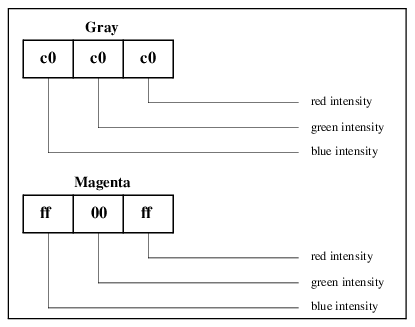
Specifying 24-bit Colors in Hexadecimal Notation
Colors in PV-WAVE graphics windows can be specified using the Color keyword. In the range of {0…16,777,216}, the color magenta has a decimal value of 16,711,935. But when using 24-bit color, the convention is to represent this value not as a decimal value, but as a 6-digit hexadecimal value. For example, the color magenta can be passed to one of the graphics routines using the construct:
Color = 'ff00ff'x
The first two digits in this hexadecimal value correspond to the blue intensity, the middle two digits correspond to the green intensity, and the right two digits correspond to the red intensity. The interpretation of the various digits is shown in
Figure B-4: Hexadecimal Notation for Colors on page 2207. The top color shown in this figure is a light gray, since the red, green, and blue components are all set to an equal intensity. The lower color shown is the color magenta, where red and green are both set to full intensity (f f), but the color green is essentially turned “off” by setting it equal to zero (00).
The hexadecimal notations for some of the most commonly-used colors are shown in
Common Color’s Hexadecimal Notation.
note | When programming with WAVE Widgets or Widget Toolbox, you can only enter colors using color names. The hexadecimal form is not recognizable by the WAVE Widgets or Widget Toolbox routines. For more information about how to select colors for widgets in a graphical user interface (GUI), refer to the PV‑WAVE Application Developer’s Guide. |
Specifying 24-bit Plot Colors
In the TrueColor visual class, raster graphics colors go through the translation table, but vector graphics colors do not. This means that vector graphics colors in plots can be specified explicitly despite any translation table that has been loaded.
For more information about the translation table, refer to
"Color Translation Table".
Example—Plotting with 24-bit Colors
The following example plots a line chart showing five data sets, each one plotted in a different color. (Assume that mydata1, mydata2, mydata3, mydata4, and mydata5 have all been defined as integers or floating-point vectors prior to entering the commands shown below.)
; Define a TrueColor graphics window.
DEVICE, True_Color=24
; Draw mydata1 using a green line.
PLOT, mydata1, Color='00ff00'x
; Draw mydata2 using a red line.
OPLOT, mydata2, Color='0000ff'x
; Draw mydata3 using a blue line.
OPLOT, mydata3, Color='ff0000'x
; Draw mydata4 using a yellow line.
OPLOT, mydata4, Color='00ffff'x
; Draw mydata5 using a orange line.
OPLOT, mydata5, Color='007fff'x
note | The system variable !D.N_Colors must still be initialized properly prior to opening the graphics window. For more information about how to initialize color characteristics, refer to
"When Color Characteristics are Determined". |
Write Mask and Graphics Functions to Manipulate Color
If you are using PV‑WAVE in one of the 24-bit visual classes, you may want to consider using the write mask to isolate a certain group of bits, such as the red group of bits, or the green group. This is relatively easy to do, since each pixel in video memory directly references a set of three 8-bit red-green-blue intensities. For more information about how to address the various planes of a 24-bit (24-plane) workstation, refer to
"Understanding 24-bit Graphics Displays".
In an 8-bit visual class, an analogous write mask operation is to use a write mask of 1 so that only the “lowest” plane is affected. But this is a suitable choice only if you want to force your application to display in monochrome on both color and monochrome displays.
note | For best results when using the write mask, use a color table that uses all 256 available colors, and bypass the translation table to make sure the color table starts at zero (0). Unfortunately, a side effect of letting PV‑WAVE allocate all 256 colors is that you may see “window flashing” when using your application, as explained in
"Private Colormaps". |
Using the Write Mask to Create Special Effects
The write mask can be used to superimpose (overlay) one graphics pattern over another when plotting to a graphics window, allowing you to create special effects. For example, some 24-bit displays allow the screen to be treated as two separate 12-bit Pseudo_Color visuals. This allows for “double-buffering”, a technique useful for animation, or for storing distance data to simplify hidden line and plane calculations in 3D applications.
Another possible application for the write mask is to simultaneously manage two 4-bit-deep images in a single graphics window instead of a single 8-bit-deep image. Use the write mask to control whether the current graphics operation operates on the “top” image or the “bottom” image.
Using Graphics Functions to Manipulate Color
PV‑WAVE’s X (and Windows) driver provides two keywords for inquiring and manipulating the graphics function—Get_Graphics_Function and Set_Graphics_Function.
The value of the
Set_Graphics_Function keyword controls the logical graphics function; this function specifies how the source pixel values generated by a graphics operation are combined with the pixel values already present on the screen. To see a complete list of graphics function codes, refer to the
Set_Graphics_Function keyword description in the section
"X Window System".
For example, the following code segment shows how to use the XOR graphics function to toggle the “low bit” of the pixel value that determines the color in a rectangle defined by its diagonal corners (x0, y0) and (x1, y1):
; Set graphics function to exclusive or (GXxor), saving the old
; function.
DEVICE, Get_Graphics=oldg, Set_Graphics=6
; Use POLYFlLL to select the area to be inverted, and immediately
; XOR a pixel value of 1 with the image currently displayed in
; that area. XORing every pixel with the binary equivalent of 1
; ensures that only the lowest bit of the color is affected.
POLYFILL, [[x0,y0], [x0,y1], [x1,y1], [x1,y0]], /Device, Color=1
; Restore the previous graphics function.
DEVICE, Set_Graphics_Function=oldg
The default value for Set_Graphics_Function is GXcopy, which means that the source graphics from the current operation get copied into the window, destroying any graphics that were previously displayed there.
Interaction Between the Set_Write_Mask and the Set_Graphics_Function Keywords
Use the Set_Write_Mask keyword to specify the planes whose bits you are manipulating or the plane you want to use for the special effects. The way the two graphics patterns are combined depends on the value you provide for the Set_Graphics_Function keyword. For example, the following commands:
DEVICE, Set_Graphics_Function=6
DEVICE, Set_Write_Mask=8
extract the fourth bit (the binary equivalent of the decimal value 8) of the image in the current graphics window. The extracted plane is XORed (XOR is the graphics function specified by setting the Set_Graphics_Function keyword equal to 6) with the source pattern (the result of the current graphics operation). After the graphics function is implemented, the result is drawn in the current graphics window using whichever color(s) in the color table match the resultant value(s).
Interaction Between the Set_Graphics_Function Keyword and Hardware Pixel Values
The graphics functions specified by the Set_Graphics_Function keyword operate on hardware pixel values. Unless the translation table is bypassed, like it is when displays with static (read-only) visual classes and private color tables are used, a color table index that represents a certain color will likely differ in value from the hardware pixel value that represents the same color. This can produce unexpected colors when you use the GX graphics functions.
An easy way to avoid getting such unexpected colors is to use Boolean OR, AND, XOR, and NOT operators, rather than the GX graphics functions. For details, see the following example.
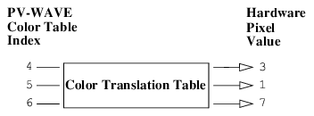
Example—Understanding the Colors that are Produced by the GX Graphics Functions
Suppose that you are using your X display in one of the 8-bit visual classes, and
Color Translation Table shows a simple color translation table.
Now enter the following commands:
; Define a simple dataset to experiment with.
data = [1, 2, 3]
GXand = 1
; The data is plotted in hardware color 1, because color 5 gets
; translated to hardware pixel value 1.
PLOT, data, Color=5
; The data is plotted in hardware color 3, because 5 ANDed with 6
; equals 4, which then gets translated to hardware pixel value 3.
PLOT, data, Color=(5 AND 6)
; The data is plotted in hardware color 1, because color 5 is
; translated to hardware pixel value 1 and color 6 is translated
; to hardware pixel value 7. Then, in hardware pixel values, 7
; is ANDed with 1 and the result equals 1.
DEVICE, Set_Graphics_Function=GXand
PLOT, data, Color=6
note | You can check the values in the current translation table using the Translation keyword; this keyword specifies the name of a variable to receive the translation vector. To read the translation table, enter this command: |
DEVICE, Translation=Transarr
The result is a 256-element byte vector, Transarr. Element zero of Transarr contains the pixel value allocated for the first color in the PV‑WAVE colormap, and so forth.
X Window IDs
PV‑WAVE provides methods for getting and setting X Window IDs for any PV‑WAVE window. PV‑WAVE also supports methods for setting and getting X Pixmap IDs for PV‑WAVE windows.
To set the X Window ID for a PV‑WAVE window, use the Set_Xwin_Id keyword with the WINDOW procedure. The X Window ID must be a valid, existing ID for the X server that PV‑WAVE is using. When the Set_Xwin_Id keyword is used, PV‑WAVE uses the X window associated with the ID; PV‑WAVE does not create a new window. The programmer is responsible for synchronizing this window by the two programs.
note | If the X Window ID is from another program, PV‑WAVE color table changes may not affect the window. |
To get the X Window ID for a PV‑WAVE window, use the Get_Win_ID keyword with the WINDOW procedure. The X Window ID returned from the WINDOW procedure may be passed to another program. The other program may then write into the PV‑WAVE window. The programmer is responsible for synchronizing this window by the two programs.
Similarly, the Get_Xpix_Id keyword can be used to get the X Pixmap ID.
Caution | The WDELETE procedure will delete all windows sharing a common X Window ID. For example: WINDOW, 0, Get_Xwin_Id=New_Xwin_Id WINDOW, 1, Set_Xwin_Id=New_Xwin_Id WDELETE, 1 The command WDELETE, 1 deletes both windows 1 and 0. |
Version 2017.1
Copyright © 2019, Rogue Wave Software, Inc. All Rights Reserved.