Transforms
Transforms, also known as transformation matrices, are an essential part of Objective Views. Transformation matrices keep track of how a component has been manipulated (moved, rotated and scaled). Every component can have a transformation matrix For
CODPointComponents, the vertices of the components are transformed by the matrix before they are drawn to position the component.
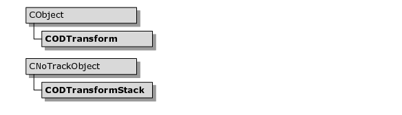
Figure 71 shows the class hierarchy for transforms.
Transform Classes
Objective Views has two transform classes.
CODTransform
This class encapsulates a two-dimensional transformation matrix. Manipulating these matrices is a simple process. You can change the matrix to reflect movement, rotation, and scaling. You can also combine matrices together to combine their effects. The transform class also provides methods for transforming points using the matrix.
CODTransformStack
The transform stack is used to keep track of the effects of nested matrices. For example, a composite component might have children and grandchildren that have their own transformation matrices. To aid in the drawing of these components, a stack of transformation matrices and combinations of matrices are kept for drawing components at different levels in the hierarchy.
The transform stack is an internal detail of the Objective Views drawing system. In all likelihood, you will not need to use it.
Transformation Matrices
Transformation matrices are used in two-dimensional graphics to apply movement, rotation, scaling and shearing to a series of points. Objective Views uses transformation matrices frequently to manipulate graphical components. For example, when you move a polygon across the screen, you are not changing the values of its vertices, you are changing the transformation matrix associated with the component. When the polygon is ready to draw itself, the transformation matrix is applied to the vertices of the polygon and each line appears in the proper place in the window.
If we were just moving the components around the screen, the overhead necessary to support a transformation matrix might be large. After all, the end result is that all of the vertices in a component have an integer offset added to them. The matrices are valuable for other operations: rotation, scaling and shearing. Although the points of components are stored in integer form, these three activities require floating point math. After several complex operations, the error resulting from rounding floating point results to integers for storage becomes apparent. This is most apparent when you use the undo and redo capabilities of Objective Views. If you use the undo and redo capability without using transformation matrices, a rotated component is not set to its original position when you undo the rotation due to a rounding error.
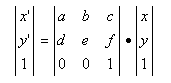
A transformation matrix is three by three. Because we are working in two dimensions, the last row is not used.
In two-dimensional space, a set of x and y coordinates can be transformed using the formula shown in
Figure 73.
The individual elements have different meanings for different operations. C and F determine the translation (or movement) of a point. A, B, D and E address the rotation, scaling and shearing of a point.
For more information on transformation matrices, look up the XFORM structure in the Visual Studio online help. XFORM is used in Windows to perform transforms when drawing to a device context.
Using CODTransform
The CODTransform object encapsulates a two-dimensional transformation matrix. To save space, only the first two rows of the matrix are stored. The class contains many methods that make it easier to use transformation matrices. You can change the translation, rotation and scaling that the matrix represents. The class also includes overloaded operators that address matrix multiplication. When you are ready to transform a point or series of points, call the appropriate transform method in this object.
Components and Transformation Matrices
Every component can have a transformation matrix. When that component is manipulated by either the user or the programmer, its transformation matrix is updated. If the component did not have a transformation matrix initially, one is created for it. You can access the current transformation matrix of any component by calling GetTransform(). If the component has no matrix, this method returns NULL.
Because the original points that comprise the component remain the same, you are changing the coordinate system of the component, not the coordinates themselves. For example, if you called Translate(50,50) on a rectangle component with its corners at (0,0) and (100,100), the application would create a transformation matrix that holds all the translation information for the component instead of moving the corners of the rectangle to (50,50) and (150,150). When the transformation matrix is created, the corners of the rectangle remain at (0,0) and (100,100), but the transformation matrix is applied to the coordinates so the rectangle appears at (50,50) to (150,150). The rectangle’s set of coordinates has not changed, but the meaning of the coordinates has changed. You have altered the coordinate system of the rectangle.
A transformation matrix for a component transforms the points of the component from its own, local coordinate system to its parent’s coordinate system. In this particular case, the transformation matrix is transforming (0,0) and (100,100) from the rectangle’s own local coordinate system to the world coordinates of the canvas, which appear as (50,50) and (150,150).
Child Components
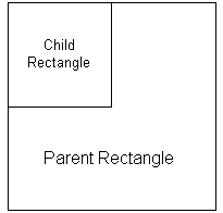
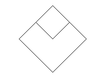
Now consider adding a child component to the rectangle discussed in the last section. Let’s add another rectangle to the component to make it a composite component, which is a component comprising several different primitive components. In this case, the original rectangle is the parent and the new rectangle is the child.
Now let’s position this new child rectangle at the upper left corner of the parent rectangle and then extend to the center. The composite component appears as in
Figure 74.
So, if the parent rectangle’s corners are at (0,0) and (100,100), and it has a transformation matrix that translates the rectangle (50,50), where should the corners of the child be?
Remember that the parent rectangle has its own coordinate system. When you add a child to a component, it is within its parent’s coordinate system. The child knows the parent’s corners are at (0,0) and (100,100). So, when you add a child, the new rectangle has its corners at (0,0) and (50,50).
The advantage of this system of nested transforms is two-fold:
• The first advantage is that you can only manipulate the children of a composite component with respect to the parent. This ensures that you can always add a child rectangle from (0,0) to (50, 50) to the parent rectangle regardless of the parent rectangle’s location and properties (rotated, scaled or sheared).
• The second advantage is that you do not need to store a transform for each child component of a composite object. For instance, if you rotated a composite composed of 100 child components, the application would only create a transformation matrix for the parent component. The 100 children would all remain relative to the parent’s coordinate system, so they could all rotate without storing their own transformation matrices.
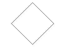
Figure 75 and
Figure 76 show samples of component manipulation.
Nested Transformation Matrices
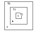
You can associate a transformation matrix with each component. If you want, you can combine these matrices. You can concatenate a series of transformation matrices into one matrix. For example, suppose the following list of conditions, pictured in Figure X, were true:
• You have a rectangle (A) that has one child rectangle (B).
• The child rectangle (B) contains another child rectangle (C), which is referred to as the grandchild.
• Each triangle has its own transformation matrix (T0, T1, T2).
To convert the grandchild into the child’s coordinate system, apply T2 to its coordinates. To convert those transformed coordinates to the parent’s coordinate system, you would transform the result of the first operation with T1. Finally, to convert those coordinates into the global coordinate system, you would transform the last result with the T0 matrix.
Alternatively, you could combine the three transformation matrices and then transform the grandchild’s points once. To do this, multiply the three matrices together:
T’ = T0 · T1 · T2
Then, you could transform the points of the grandchild with T to put them in the global coordinate system. Note that order does matter when multiplying matrices. If you reversed the order of the formula above, the grandchild would be placed in another section of the canvas.
Let’s consider another example. Again, suppose the following list of conditions were true:
• You create a composite like the one described in the previous example.
• You created the grandchild first.
Under these circumstances, you could combine the three matrices, apply that transformation to the grandchild’s points and then draw it. Next, we could take the combination of T0 and T1, apply the result to the child’s points and draw it. Finally, we could take T0, apply it to the parent’s coordinate and draw it. With more complex composites, this can lead to a lot of matrix combinations. To reduce the amount of matrix multiplication, Objective Views uses a transform stack to store intermediate matrix calculations.
How the Transform Stack Works
The CODTransformStack object is a thread-safe class that holds a list of transformation matrices. During the drawing process, CODTransformStack is used to cache the combined transformation matrices for the individual layers in a composite component like the one described in the previous section. If you were working with a component that consisted of a parent, a child and a grandchild, the drawing would follow this logic:
1. Move to the Parent level, and add the Parent’s matrix to the head of the list.
Transform Stack = [TO]
2. Move to the Child level, multiply the matrix at the head of the list by the Child’s matrix, and then add the result to the head of the list.
Transform Stack = [TO · T1] [T0]
3. Move to the Grandchild’s level, multiply the matrix at the head of the list by the Grandchild’s matrix and add the result to the head of the list.
Transform Stack = [TO · T1 · T2] [TO · T1] [T0]
4. Get the matrix at the head of the list, transform the Grandchild’s points and draw it.
Transform Stack = [TO · T1 · T2] [TO · T1] [T0]
5. Remove the matrix at the head of the list and move to the Child’s level.
Transform Stack = [TO · T1] [T0]
6. Get the matrix at the head of the list, transform the Child’s points and draw it.
Transform Stack = [TO · T1] [T0]
7. Remove the matrix at the head of the list and move to the Parent’s level.
Transform Stack = [T0]
8. Get the matrix at the head of the list, transform the Parent’s points and draw it.
Transform Stack = [T0]
9. Remove the matrix at the head of the list.
Transform Stack = empty