Layout Algorithms
This section describes each of the main layout algorithms provided with the layout manager component.
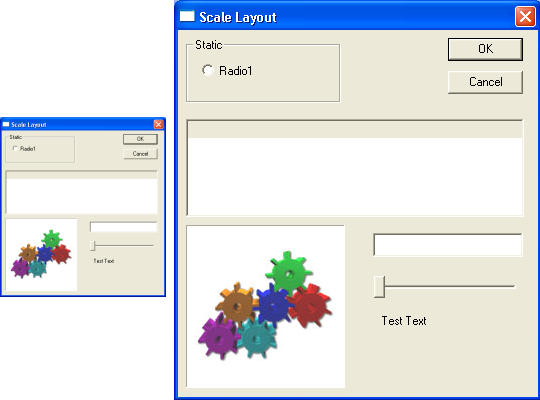
Scale Layout
The
scale layout maintains all children with a constant aspect ratio to the parent scale node. In other words, the child node’s top, left, right, and bottom coordinates are stored as percentages of the parent node’s size and are resolved to actual pixel values with each recalculation, as seen in
Figure 5. This guarantees a constant aspect ratio, regardless of the size of the parent node.
Relative Layout
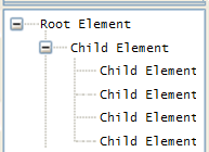
The relative layout allows a logical organization of layout nodes. The arrangement of child windows is specified as a set of constraints, which are constructed using English-like semantics.
For example:
• “Set the left side of node 1 equal to the right side of node 2 plus 10 pixels,” or
• “Set the bottom of node 1 to 25 percent of the height of node 2,” or
• “Move node 1 such that its bottom is equal to the top of node 2 – 10 pixels.”
The IRelativeLayout interface, directly derived from the ILayoutNode interface, provides an additional method SetConstraint(), which is used to specify the constraints to be used by a determined instance of the CRelativeLayout class.
Thus, you can say in your program:
pRelative->SetConstraint(pSplitter, foundation::RelLeft, pNameNode,
foundation::RelRight, 20);
which can be translated to plain English as: “Set the left side of the node pSplitter to the right side of the pNameNode node plus 20 units.”
The constraint:
pRelative->SetConstraint(pOkNode, foundation::RelMoveBottom,
pRootNode, foundation::RelBottom, -30);
can be interpreted as: “Move (without resizing it) the node pOkNode, such that its bottom is 30 pixels up from the Root node bottom.”
As an additional example, the constraint:
pRelative->SetConstraint(pOkNode, foundation::RelWidth, pRootNode,
foundation::RelWidth, 0, 0.5);
can be interpreted as: “Set the width of the pOkNode node to be 50% of the width of the Root node.”
For a description of all the options available for specifying constraints, consult the Stingray Foundation Library Class Reference.
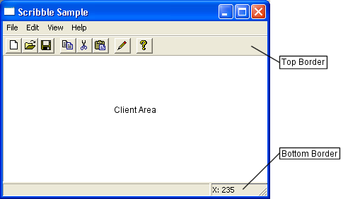
Border-Client Layout
The border-client layout implements the typical arrangement found in frame windows. Four designated areas are attached to each border of the window, where items like toolbars and status bars are usually placed. The rectangular space between these borders is generally called the client area.
To provide the additional functionality, the node class CBorderClientLayout implements the specialized interface IBorderClientLayout, which in turn derives from the ILayoutNode interface. This special interface allows the assignment of a child layout node to a specific area of the arrangement. An overload of the AddLayoutNode method is used, which takes an extra parameter to specify the area inside the window to which the child node should be assigned. For example:
pBorderClient->AddLayoutNode(pClientNode,
IBorderClientLayout::BorderPosition::Client);
assigns the pClientNode node to the Client area of the pBorderClient node.
The ILayoutNode::AddLayoutNode() method should not be used with a border-client node.
DC Layout Nodes
Rather than one concrete class, CDCLayoutBase is a templatized class. You can use CDCLayoutBase as a base class for layout node classes that need to draw directly on the device context of the window associated with their root node.
Classes derived from CDCLayoutBase should override the OnPaint() virtual method to process the specific display logic. For example, border nodes are special classes of DC nodes that decorate the surroundings of another node. They will be described later in this section.
If you want to display an image directly on your window, but you want that image to be laid out as though it were an independent visual component, you can derive a class from CDCLayoutBase and alter the OnPaint() method to display your image in the rectangle assigned to your node.
CDCLayoutBase also defines two virtual methods, PrepareDC() and RestoreDC(), that allow derived classes to manipulate the device context before the actual drawing process takes place.
NOTE >> A node class that overrides PrepareDC() and changes parameters in the device context must also override RestoreDC() and restore the device context to its original state.
The default version of PrepareDC() executes the following manipulations:
• Sets the clipping region of the device context to the intersection of the current clipping region and the rectangular region assigned to the node. The purpose of this is to make sure the DC node instance does not draw outside its boundaries.
• Offsets the viewport origin of the device context to the NonClientOffset attribute of the node. The Get and Set operations for this attribute are declared in the ILayoutNode interface, implemented by all layout nodes.
Your CDCLayoutBase-derived node class can perform different operations in these methods, but it is important to remember always to undo in RestoreDC() all what is done in PrepareDC().
Splitter Layout
The splitter layout, unlike the rest of the layout algorithms, is a “dynamic” layout arrangement. An application user can rearrange windows interactively, using the mouse. In the other layout algorithms, the layout recalculation is triggered indirectly by operations such as resizing the container window.
CSplitterLayout implements the splitter functionality in SFL. This class derives from CDCLayoutBase, which means that the splitter is not really a window, but it is drawn on the area of the window associated with the layout manager’s root node.
To perform their function, the splitters need to process mouse messages, so the window must not absorb those messages in its own message map. As explained in
“Integration with ATL”, the window must allow messages to reach the layout manager, which can rout them within the layout tree.
There are several configuration options you can specify for a splitter node, all of which change the way the user interface behaves. These options are defined in the enumerated type SplitterFlags, and are manipulated with the SetSplitterFlags() and GetSplitterFlags() methods in the ISplitter interface. SFL splitters support real-time dragging, in which the windows in the cells of the splitters are resized during the drag operation, as well as the more traditional tracking rect drag, in which a visual aid represents the result of the dragging operation but the actual windows are resized only after the user releases the mouse button. Real time dragging is used if the SplitterRealTimeDrag flag is specified.
You can disable dragging altogether in a splitter layout node, by specifying the SplitterNoSplitters flag. The result is a simple rearrangement of the child nodes in a grid, with no interactive recalculation. You can get this effect with a splitter node because the splitter layout has no specific grid layout algorithm.
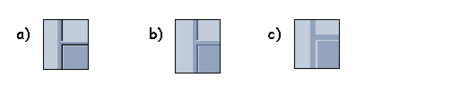
The splitter layout supports three graphic representations:
• The traditional 3-D display similar to the MFC splitter.
• A flatter display similar to the splitters in the Visual Basic and Visual InterDev development environments.
• A 2-D display like the one found in Microsoft Outlook and other Microsoft Office applications.
Which option is used by a specific instance of the
CSplitterLayout class is specified using the
SetDrawingStyle() method in the
ISplitter interface and the enumerated type
SplitterDrawingStyle.
Figure 7 illustrates the difference in appearance of these three drawing styles.
Example 52 illustrates how to set up a splitter in your window’s override of
InitLayout().
Example 52 – Setting up splitter layout
pRootNode = CreateLayoutNode(__uuidof(CSplitterLayout));
ISplitter* pSplitter = guid_cast< ISplitter*>(pRootNode);
// Use the Flat splitter style, and real time drag
pSplitter->SetDrawingStyle(foundation::DrawFlat);
pSplitter->SetSplitterFlags(SplitterRealtimeDrag);
ILayoutNode* pNode;
pNode = CreateLayoutNode(__uuidof(CWindowLayoutNode));
pNode->Init(m_hWnd, GetDlgItem(IDC_LABEL));
pSplitter->AddPane(pNode, 0, 0);
// Span the list in one column, two rows
pNode = CreateLayoutNode(__uuidof(CWindowLayoutNode));
pNode->Init(m_hWnd, GetDlgItem(IDC_LIST));
pSplitter->AddPane(pNode, 0, 1, 2, 1);
pNode = CreateLayoutNode(__uuidof(CWindowLayoutNode));
pNode->Init(m_hWnd, GetDlgItem(IDC_NAME));
pSplitter->AddPane(pNode, 0, 2);
pNode = CreateLayoutNode(__uuidof(CWindowLayoutNode));
pNode->Init(m_hWnd, GetDlgItem(IDOK));
pSplitter->AddPane(pNode, 1, 0);
pNode = CreateLayoutNode(__uuidof(CWindowLayoutNode));
pNode->Init(m_hWnd, GetDlgItem(IDCANCEL));
pSplitter->AddPane(pNode, 1, 2);
Borders and Edges
Border nodes are layout nodes that embellish the node they contain with some kind of graphic decoration around the area assigned to the contained node. Two kinds of border nodes are provided with SFL’s layout package: edges and grippers. All border nodes implement the specialized interface IBorderLayout.
An edge border is implemented in the CBorderEdge class. The border edge draws a 3-D border line around the node. The node can be configured to draw the line on any combination of the four borders of the contained node area.
Gripper nodes display a gripper area either at the top (for vertical grippers) or at the left (for horizontal grippers) of the contained node. In addition, in the borders where a gripper is not drawn, blank space can be left to give an appearance of separation between distinct elements.
All border nodes implement IBorderLayout. This interface, which derives directly from ILayoutNode, publishes methods for setting or getting the size of the borders or the border orientation, and for showing or hiding the border decoration. The default implementation of this interface is provided in the CBorderLayoutBase template class.
Edges and grippers derive from a more specialized class, CBorderGraphic. CBorderGraphic derives from CBorderLayoutBase, but it is designed to use the class CDCLayoutBase as its base class. This allows the CBorderGraphic derivatives, like CBorderEdge and CGripperWrapper, to paint directly in the device context of the window associated with the root node of the layout tree.
To add a border wrapper to some interface element of your application (such as a window or image), you have to instantiate the appropriate border layout class and add the layout node associated with your interface element as the border node child.
Example 53 shows how to do this.
Example 53 – Adding a border wrapper to an interface element
pWrapper = CreateLayoutNode(__uuidof(CGripperWrapper), pWrapper);
pWrapper->Init(*this);
ILayoutNode* pListNode =
CreateLayoutNode(__uuidof(CWindowLayoutNode));
pListNode->Init(*this, m_wndList);
pWrapper->AddLayoutNode(pListNode);