FREQTRANS Function (PV-WAVE Extreme Advantage)
Performs frequency transformation of a lowpass prototype filter (in the normal filter structure) H(z) into another filter G(z) by replacing z with a stable all-pass filter F(z).
Usage
result = FREQTRANS(h[, p])
Input Parameters
h—Digital filter structure. If you want to use one of the four predefined standard transformations, this filter is assumed to be lowpass, by convention.
p—(optional) An array of polynomial coefficients in z–1. This polynomial is optional, and will be generated for you if you use one of the standard transformations: lowpass, highpass, bandpass, or bandstop.
Returned Value
result—A filter structure containing the transformed filter.
Keywords
Bandpass—[oldcutoff, lowcutoff, upcutoff] Where oldcutoff is the cutoff frequency of the prototype lowpass filter; lowcutoff is the lower cutoff frequency; and upcutoff is the upper cutoff frequency. Note that upcutoff – lowcutoff cannot equal oldcutoff.
Where oldcutoff is the cutoff fre quency of the prototype lowpass filter; lowcutoff is the lower cutoff frequency; and upcutoff is the upper cutoff frequency. Note that upcutoff - lowcutoff cannot equal oldcutoff.
Bandstop—[oldcutoff, lowcutoff, upcutoff] Where oldcutoff is the cutoff frequency of the prototype lowpass filter; lowcutoff is the lower cutoff frequency; and upcutoff is the upper cutoff frequency.
Highpass—[oldcutoff, newcutoff] Where oldcutoff is the cutoff frequency of the lowpass filter to be transformed; newcutoff is the cutoff frequency of the transformed filter returned.
Lowpass—[oldcutoff, newcutoff] Where oldcutoff is the cutoff frequency of the lowpass filter to be transformed; newcutoff is the cutoff frequency of the transformed lowpass filter returned.
Newname—If the Newname parameter isn’t passed in, the new filter structure has the same name as the old one.
Sigma—Set to 1 to return a lowpass filter and –1 for a highpass filter. (Default: Sigma = 1)
Discussion
Keywords are used to specify one of four standard transformation types. Each of the keyword parameters used to call a standard transform accepts an array, and each array requires that a new cutoff frequency be specified. These new frequencies should be normalized between 0 and 1.
Once this is done, a complementary polynomial to p(z) is created. The two polynomials are related as:
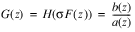
The transform itself is given by:
where:
is a stable all-pass filter and:
p(z) = p0 + p1z–1 + p2z–2 + ...
The numerator polynomial p is a polynomial in z–1, such as the FREQTRANSDESIGN function creates.
note | Keep the following points in mind when using FREQTRANSDESIGN:  Do not use a transformation order that is very high. The resulting high order filter may be numerically unstable. If polynomial p is obtained using FREQTRANSDESIGN, the lowpass prototype filter H( z) must have a normalized frequency cutoff of 0.5. The polynomial p must be stable and pass the Schur-Cohn test. Otherwise, FREQTRANS will fail. |
Example
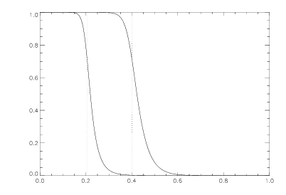
This example generates a lowpass Butterworth filter and then moves the cutoff frequency (
Lowpass Butterworth Filter with Shifted Cutoff Frequency).
fp = 0.2049
n = 8
; Define an eighth-order Butterworth filter.
h = IIRDESIGN(n, fp, /Butter)
newfp = 0.4
; Now, move the cutoff frequency from 0.2049 to 0.4.
result = FREQTRANS(h, Lowpass = [fp, newfp])
resp = ABS(FREQRESP_Z(result, Outfreq = freq))
newresp = ABS(FREQRESP_Z(h, Outfreq = freq))
; Plot original lowpass Butterworth filter frequency response.
PLOT, freq, resp
; Plot the frequency response with the shifted cutoff frequency.
OPLOT, freq, newresp
REFLINES, [fp, newfp]
See Also
For Additional Information
Parks and Burrus, 1987.
Proakis and Manolakis, 1992.
Roberts and Mullis, 1987.
Version 2017.0
Copyright © 2017, Rogue Wave Software, Inc. All Rights Reserved.